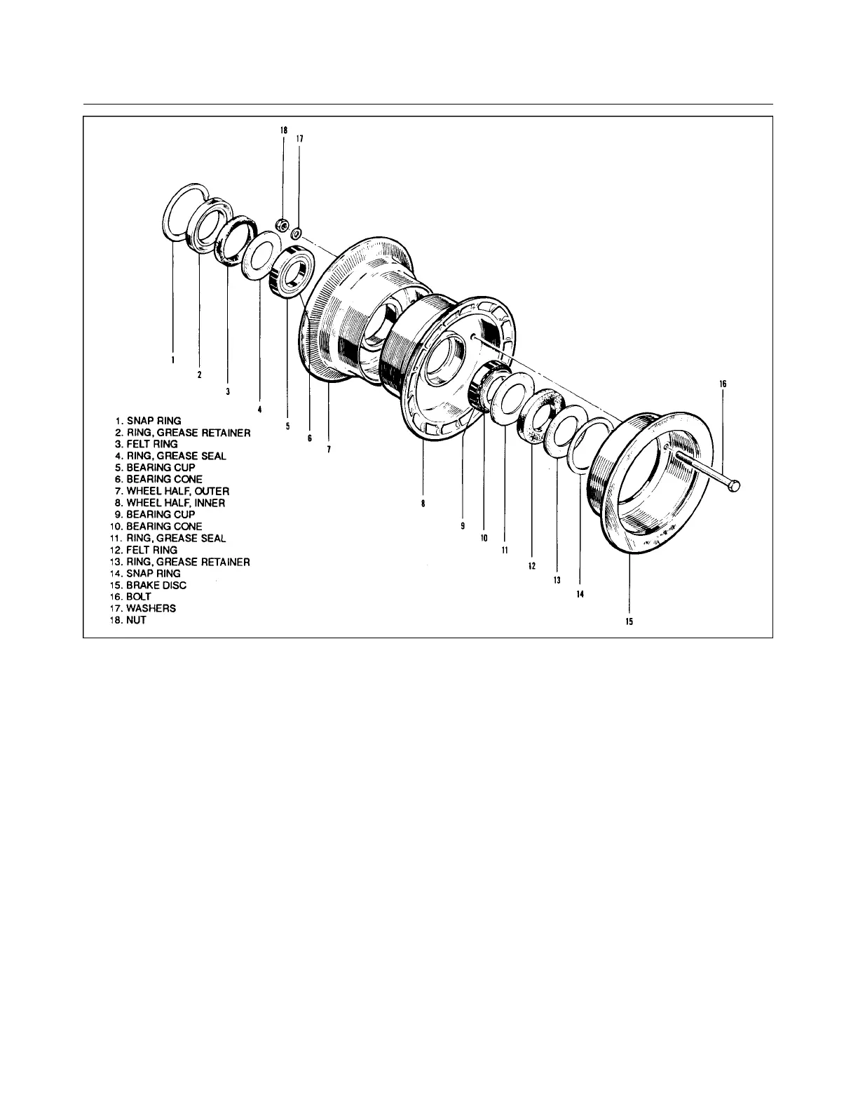
Figure 7-17. Main Wheel Assembly
7-49. INSPECTION OF MAIN WHEEL ASSEMBLY. The inspection of the main wheel is the same as that
given for the nose wheel, Paragraph 7-46.
7-50. ASSEMBLY AND INSTALLATION OF MAIN WHEEL. (Refer to Figure 7- 17.)
a. Ascertain that the bearing cup (5 or 9) for each wheel is properly installed. Install the tire with tube on
the outer wheel half (7) and then join the two wheel halves. Position the brake disc (15) in the inner
wheel half and install the through bolts with the nuts on the valve stem side. Torque wheel nuts to 150
inch pounds and inflate tire.
b. Lubricate the bearing cones (6 or 10) and install the cones, grease seals (4 or 11), seal retainer rings (2
or 13) and felt rings (3 or 12). Secure with snap rings (1 or 14).
c. Slide the wheel on the axle and secure with retainer nut. Tighten the nut to allow no side play, yet
allow the wheel to rotate freely. Safety the nut with a cotter pin and install dust cover.
d. Position the brake lining back plates between the wheel and brake disc and the brake cylinder on the
torque plate. Insert the spacer blocks between the back plates and cylinders and install the four bolts to
secure the assembly. If the brake line was disconnected, reconnect the line and bleed the brakes.
Revised: 2/13/89
1K12
* CHEROKEE ARROW III SERVICE MANUAL
LANDING GEAR AND BRAKE SYSTEM