Revised: 2/13/89
2G10
CHEROKEE ARROW III SERVICE MANUAL
INSTRUMENTS
10-59. ELECTRICAL INSTRUMENTS.
10-60. TURN AND BANK INDICATOR.
10-61. GENERAL. The turn and bank indicator is an electrical instrument. The turn portion of the indicator is
driven by a permanent magnet DC governor controlled gyro motor. Damping action is provided by a precision
air dashpot. The indicator is designed to indicate the rate of turn and roll; which means, if the aircraft is rolled
right and left rapidly, the indicator will move, indicating a turn, but if the aircraft is held in a bank, by applying
r u d d e r, the indicator will come back to zero indicating no turn. The bank portion of the indicator is a ball
sealed in a curved glass tube filled with damping fluid. In an improperly coordinated turn, the ball is forced
from the center of the tube, thus indicating attitude error.
10-62. TROUBLESHOOTING.
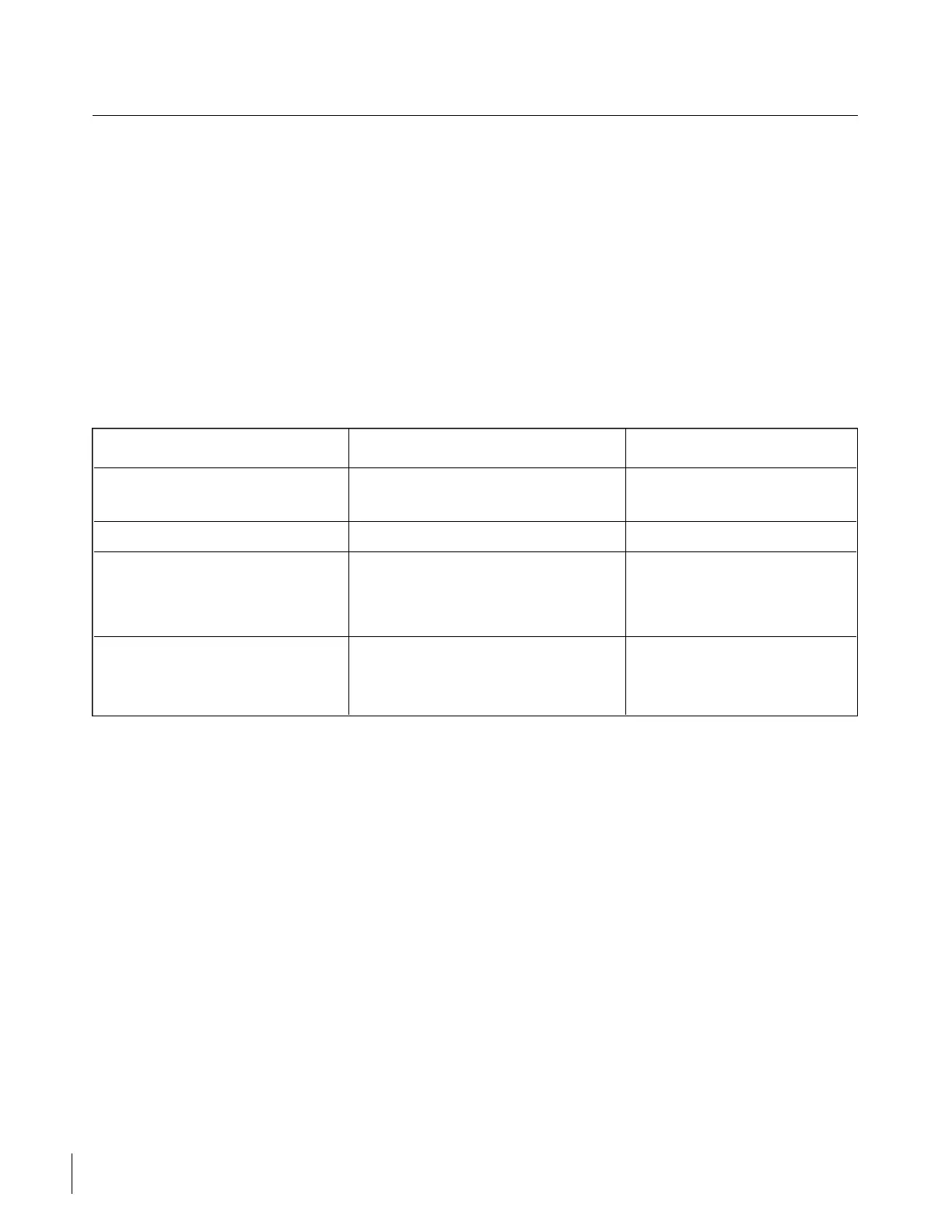
TABLE X-XII. TURN AND BANK INDICATOR
Trouble Cause Remedy
Pointer fails to respond. Foreign matter lodged in Replace instrument.
instrument.
Incorrect sensitivity. Out of calibration. Replace instrument.
Incorrect turn rate. Out of calibration. Replace instrument.
Aircraft not in Center ball in turn.
coordinated turn
Instrument will not run. No Dower to instrument. Check circuit and repair.
Instrument malfunction. Replace instrument.
10-63. REMOVAL AND REPLACEMENT. (Refer to Paragraph 10-76 of this section.)
10-64. FUEL QUANTITY INDICATOR.
10-65. GENERAL. The two quantity gauges are mounted in the cluster on the instrument panel. These
instruments are calibrated in divisions of 10, 20, 30 gallons and full. Two transmitter units are installed in each
fuel cell. These units contain a resistance strip and a movable control arm. The position of this arm is
controlled by a float in the fuel cell and this position is transmitted electrically to the indicator gauge to show
the amount of fuel in the cell.

 Loading...


