Figure 8-11. Impluse Coupling Figure 8-12. Flyweight Clearance of Impulse
Coupling
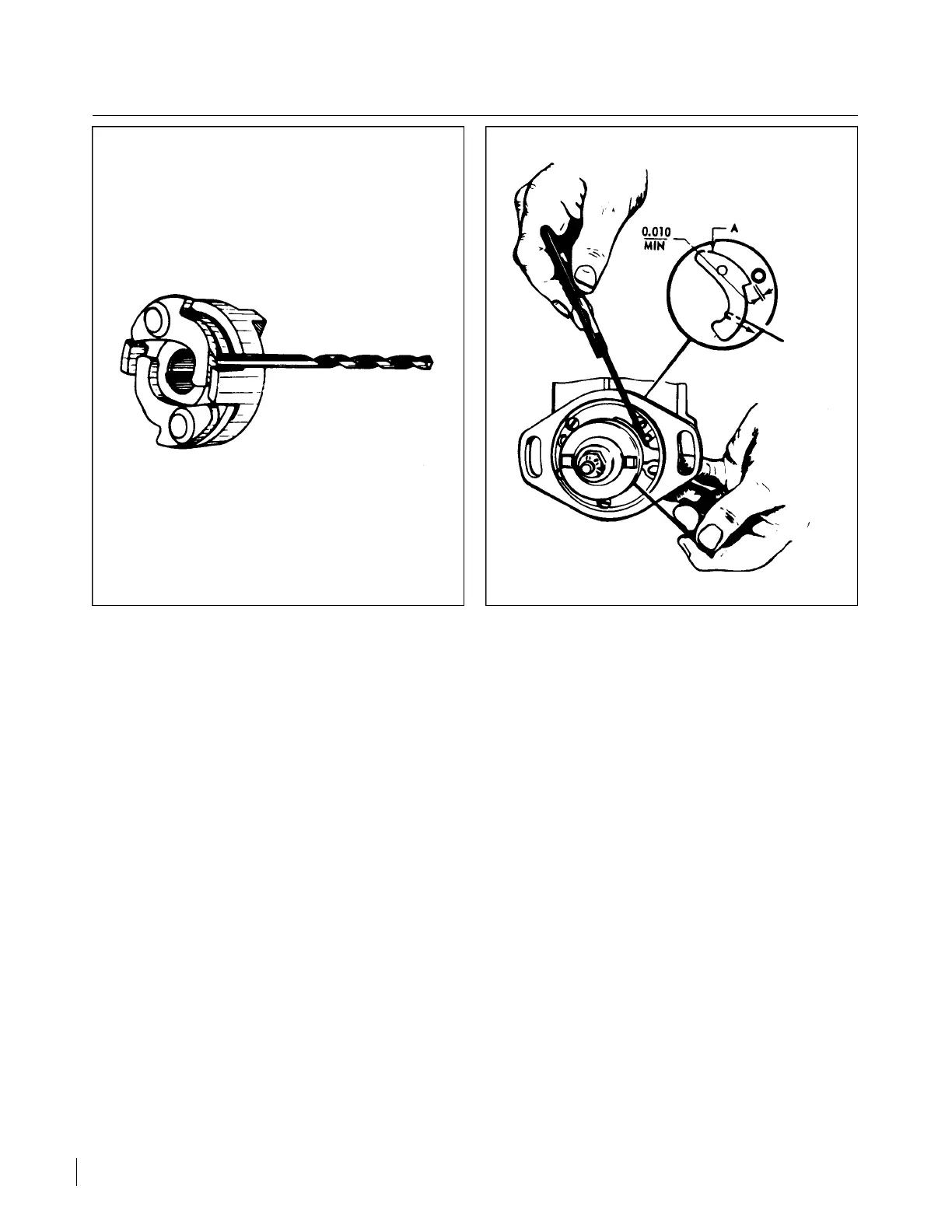
n. Check the clearance between each flyweight and each stop pin as follows:
1. Bend the end of a stiff piece of wire into a right angle 0.125 inch long (maximum).
2. Hold magneto as shown in Figure 8-12. Pull heel of flyweight outward with the hooked wire and
make certain that feeler gauge of 0.010 inch minimum thickness will pass between stop pin and
the highest point of the flyweight.
NOTE
A true and accurate check of the clearance between flyweight and stop pin
can only be obtained by pulling the flyweight outward as described above.
Do not attempt the check by pushing in on flyweight at point “A.”
o. Check internal timing and reinstall and time magneto to engine.
8-37. REMOVAL OF MAGNETO.
a. Remove the engine cowl.
b. Disconnect the “P” lead from the magneto.
c. Remove the harness outlet plate from the magneto by removing the four attaching screws.
d. Remove the two nuts and washers securing the magneto to the engine accessory housing.
e. Pull the magneto from the engine.
Revised: 8/31/77
2B10
CHEROKEE ARROW III SERVICE MANUAL
POWER PLANT - CONTINENTAL