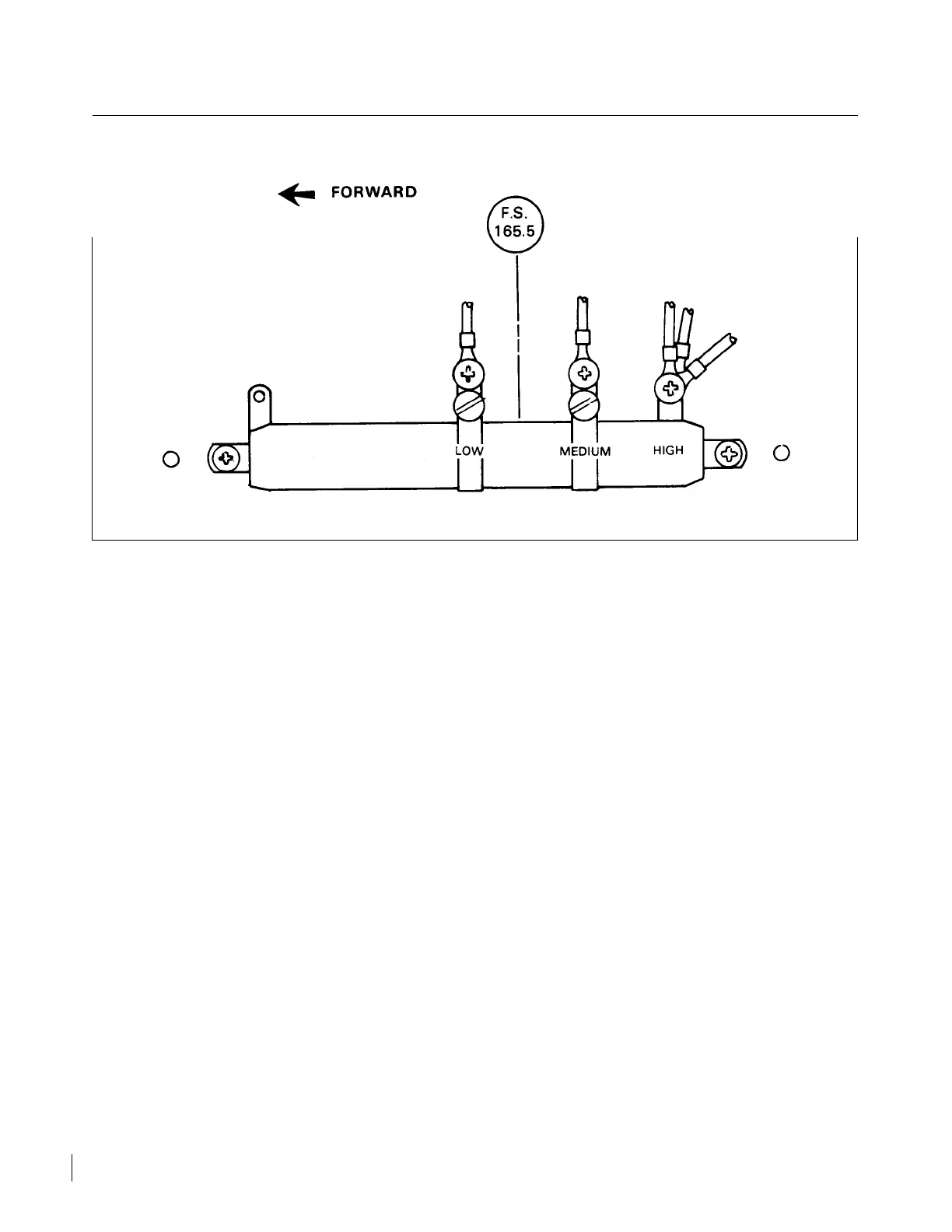
Figure 9-7. Aux Fuel Pump Variable Resistor
c. Disconnect the wire from the auxiliary pump circuit breaker.
d. From an external power source containing a voltmeter, connect the negative lead to ground and the
positive lead to the slide resistor high terminal.
e. Connect a calibrated voltmeter across the auxiliary fuel pump and adjust the external power source
until 12.0 to 12.5 volts direct current is indicated. Record the voltage reading from the external power
source.
f. Check the calibrated pressure gauge. At least 31 to 37 psi should be indicated.
g. Connect the positive lead to the LOW power terminal of the slide resistor.
h. Adjust the power supply voltage level to obtain that recorded in step e.
i. Slide the LOW terminal on the resistor to obtain a pump pressure of 8 to 10 psi.
j. Readjust power supply and LOW terminal to ensure a pump pressure of 8 to 10 psi at a power supply
voltage of the previously recorded in step e.
k. Secure the LOW terminal slider.
l. Connect the positive lead to the MEDIUM power terminal of the slide resistor and adjust the power
supply voltage level to that recorded in step e.
m. Position the MEDIUM terminal on the resistor to obtain a pump pressure of 23.5 to 24.5 psi and
readjust the power supply and terminal to ensure that pressure at a power supply voltage recorded in
step e.
n. Secure the MEDIUM power terminal and attach disconnected wires.
o. If the aircraft is equipped with a fuel diverter valve, operate the primer switch and ensure the valve is
being energized. Release the primer switch and operate the fuel pump switch in the HI-BOOST
position and ensure that the pump operates and that the diverter valve does not.
Revised: 2/13/89
2E21
CHEROKEE ARROW III SERVICE MANUAL
FUEL SYSTEM