10-16. SUCTION GAUGE.
10-17. GENERAL. The suction gauge is mounted in the right side of the instrument panel to the left and up
from the cigar lighter. This gauge is calibrated in inches of mercury and has a direct pressure line and vent line.
Therefore, the gauge indicates the differential pressure or actual pressure being applied to the gyro instruments.
As the system filter becomes clogged or lines obstructed, the gauge will show a decrease in pressure. Do not
reset the regulator until the filter and lines have been checked.
10- 18. TROUBLESHOOTING. For troubleshooting of this instrument, refer to Table X-I of this section.
NOTE
For ease of pitot line installations in later models, changes of some lines
have been made, but in no way change the design or operation of the
system.
10-19. PITOT-STATIC SYSTEMS. (Refer to Figure 10-2.) Pitot pressure for the airspeed indicator is sensed
by the pitot mast mounted under the left wing. Static pressure for the altimeter, vertical speed and airspeed
indicators is sensed by two static pressure units, one located on each side of the rear part of the fuselage.
A drain is provided in the lower left front side panel to drain moisture from the pressure line running
between the pitot mast and the instrument panel.
When installed, an alternate static source control valve is located below the instrument panel to the right of
the power quadrant. If one or more of the pitot static instruments malfunctions these pressure systems should
be checked for leaks, dirt or water. If moisture is present, the static system can be drained by turning on the
alternate static system. The selector valve is located at the low point of the system.
At any time an instrument fitting, line, pitot head or static button is disconnected, tests must be performed
prior to the next flight. Refer to AC43.13- 1 A for the testing procedures.
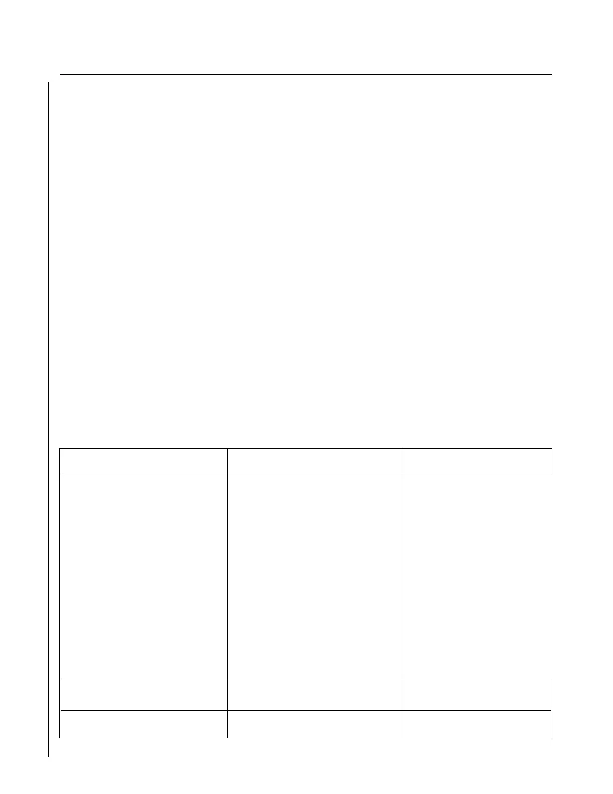
TABLE XI-II. DIRECTIONAL GYRO INDICATOR
Trouble Cause Remedy
Excess drift in either Setting error. Reset per paragraph 10-19.
direction.
Defective instrument. Replace instrument.
High or low vacuum.
If vacuum is not correct,
check for the following:
a. Relief valve a. Adjust.
properly adjusted.
b. Incorrect gauge b. Replace gauge.
reading.
c. Pump failure. c. Repair or replace.
d. Vacuum line kinked d. Check and repair.
of leaking. Check for collapsed
inner wall or hose.
Dial spins during turn. Limits (55° bank) of Recage gyro in level
gimball exceeded. flight.
Dial spins continuously. Defective mechanism. Replace.
Revised: 2/13/89
2F21
CHEROKEE ARROW III SERVICE MANUAL
INSTRUMENTS