4.27
Fuel Systems
4
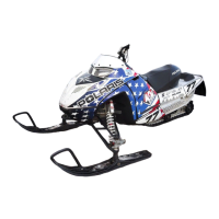
Exhaust Valve Solenoid
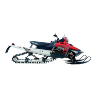
CFI Ignition Coils
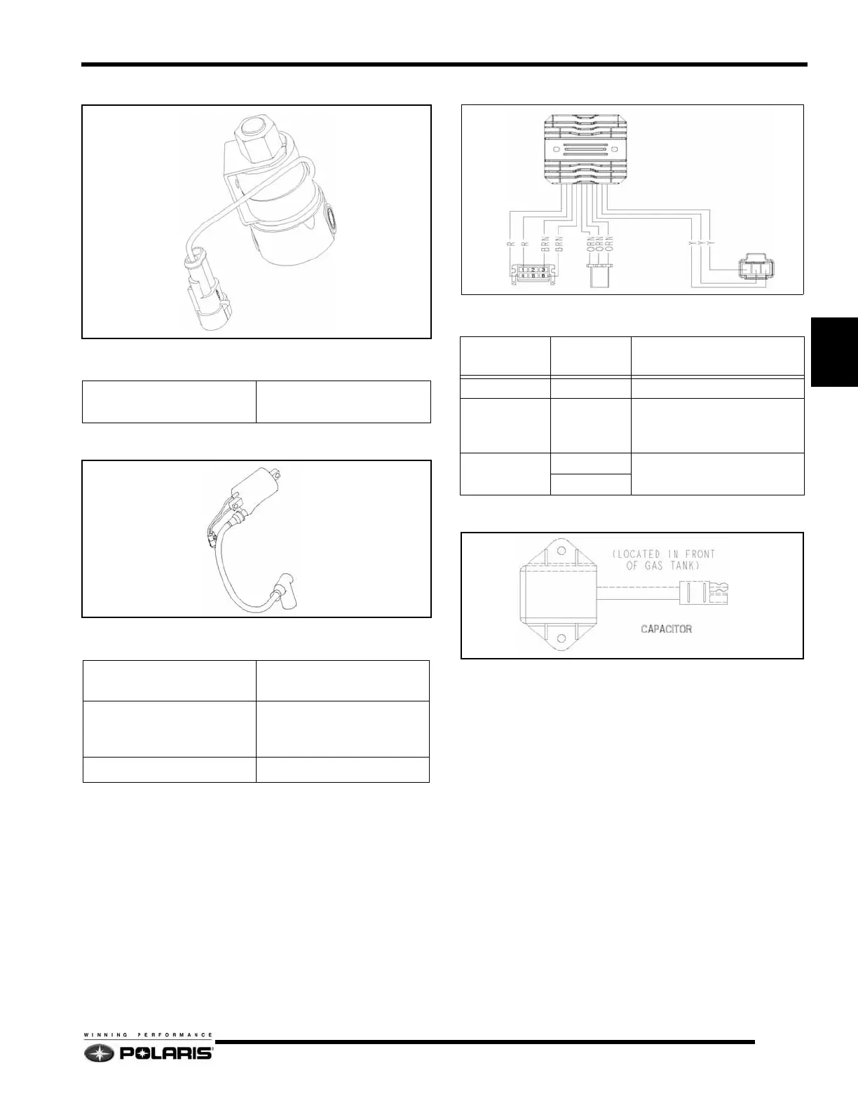
Regulator / Rectifier
Chassis Power Capacitor
Capacitor Testing
1. Charge the capacitor for 10 seconds using a 12 volt battery
by connecting the positive (+) lead to the Red/White wire
and the negative (-) lead to the brown wire.
2. Monitor the capacitor voltage with a multimeter. The
voltage should slowly drain down from the initial charge.
If the cap does not hold a charge or drains rapidly, replace
the component.
Specifications
Coil Resistance
(WHT/YEL to RED)
15Ω +/- 15% @ 68°F (20°C)
Specifications
Primary Coil Resistance
(Black to White)
0.45Ω +/- 15% @ 68°F (20°C)
Secondary Coil Resistance
(Without Plug Cap)
(Black to High Tension Lead)
18,000Ω +/- 15% @ 68°F
(20°C)
Plug Cap Resistance 4,000Ω - 6,000Ω
Regulator / Rectifier Connections
CONNECTOR
WIRE
COLORS
ITEM
STATOR YELLOW Vac from stator charge coils.
ECU ORANGE
Vdc supplied to ECU to boost
power to fuel injectors during
engine start-up.
CHASSIS
BROWN
14.5 Vdc chassis power
supply.
RED
 Loading...