5.27
Engine and Cooling Systems
5
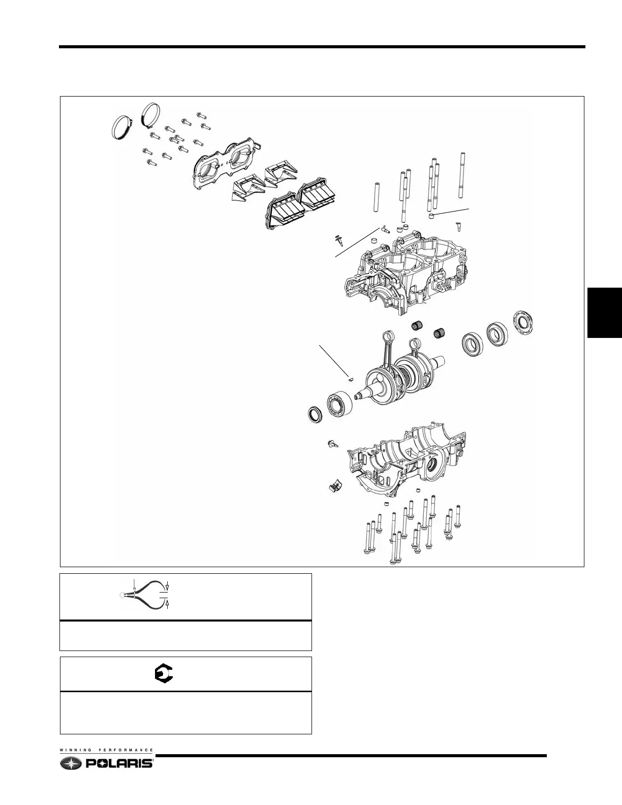
2007 - 2008 600 / 700 CFI Crankcase /
Crankshaft Assembly
1. Remove the engine from the engine compartment.
2. Follow the process for removing the cylinder head,
cylinders, pistons, flywheel / recoil housing, and the water
/ oil pump.
3. Remove the intake boots, reed stuffers, and reed assemblies
from the intake tracks. Discard any seals or gaskets.
4. Remove the fasteners from the bottom of the crankcase.
Carefully pry apart the crankcase halves. Discard the PTO
and MAG crankshaft seals.
5. Remove the crankshaft. Inspect as required.
6. Thoroughly clean the two crankcase mating surfaces with
carburetor cleaner and a gasket remover. Flush out the
crankcase galleries.
GEAR CLAMPS
INTAKE BOOTS
REED STUFFERS
REED BLOCKS
CYLINDER STUDS
NEEDLE BEARINGS
PTO SEAL
MAG SEAL
MAG BEARING
PTO BEARINGS
FLYWHEEL KEY
CRANKSHAFT
OIL INJECTION CHECK VALVE QTY. 5
ALIGNMENT DOWELS
A
B
C
= In. / mm.
Long Stud Height (Exhaust side) = 4.13" (105mm)
Small Stud Height (Intake side) = 2.16
" (55mm)
= T
A = 9 Ft.Lbs. (12 Nm)
B = 22 Ft.Lbs. (30 Nm)
C = 10 Ft.Lbs. (13 Nm) - Apply Pipe Sealant
 Loading...