5.17
Engine and Cooling Systems
5
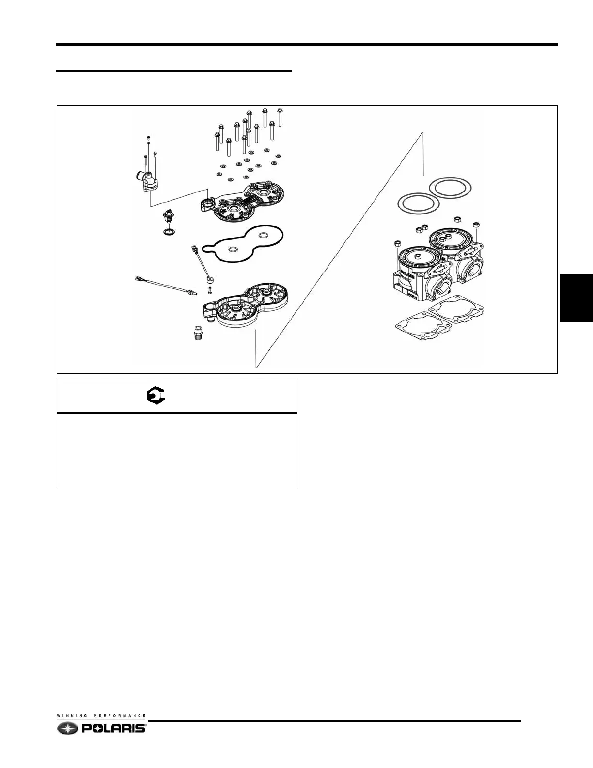
ENGINE COMPONENT ASSEMBLIES
600 HO Carbureted Cylinders / Cylinder Head
Disassembly / Assembly Process
1. Remove the coolant from the engine using a siphon, wet/
dry vac, or drain pan.
2. Remove the air box, exhaust pipe and resonator from the
engine compartment.
3. Remove the high tension wires and spark plugs from the
cylinder head.
4. Remove the thermostat housing outlet cooling hose from
the housing.
5. Loosen all, then remove all head cover fasteners. Clean the
fastener threads to remove any thread locking residue.
6. Discard the head cover and cylinder head o-rings. Always
use new o-rings during assembly.
7. Inspect the cylinder head / combustion domes for any
damage. Measure cylinder head flatness. Replace cylinder
head if required.
8. Loosen all, then remove the cylinder bolts. Clean the bolt
threads to remove any thread locking residue.
9. Carefully pull each cylinder upwards taking care not to
drop the piston and rod abruptly against the crankcase.
10. Remove the cylinder base gaskets. Use a gasket scraper to
clean the gasket residue from the crankcase and cylinder
bases.
11. Inspect the cylinder walls. Nicasil cylinders can only be
lightly honed. Damage that cannot be removed with a light
hone requires cylinder replacement or re-lining.
12. The assembly process is the reverse of disassembly.
13. Always use new gaskets and o-rings during assembly.
Liberally coat the inside of each cylinder and the outside
of each piston with Polaris two-stroke engine oil.
14. When installing a piston into a cylinder, verify each piston
ring opening is located at each piston ring locating pin.
Squeeze the top ring, then carefully slide the cylinder over
the compressed ring. Do the same with the bottom ring.
15. Follow the torque specifications and torque sequences
located at beginning of chapter when tightening fasteners.
HEAD COVER
WASHERS
CYLINDER HEAD O-RINGS
CYLINDERS
CYLINDER BASE GASKETS
CYLINDER HEAD
HEAD COVER O-RINGS
THERMO SENSOR
KNOCK SENSOR
THERMOSTAT
GASKET
THERMOSTAT
HOUSING
BLEED SCREW
A
B
C
D
E
F
= T
A = 70 In.Lbs. (8 Nm)
B = 9 Ft.Lbs. (12 Nm) - Apply Loctite 242
C = 25 Ft.Lbs. (34 Nm) - Apply Loctite 242
D = 18 Ft.Lbs. (24 Nm) - Apply Pipe Sealant
E = 168 In.Lbs. (19 Nm) - Clean and Dry
F = 37 Ft.Lbs. (50 Nm)
 Loading...