11.7
Battery and Electrical Systems
11
THROTTLE POSITION SENSOR (TPS)
The TPS is located on the carburetor rack (carbureted engines)
or on the throttle body (CFI engines). The TPS is set at the time
of manufacture and should only require adjustment when:
• When the TPS is replaced.
• When the carburetor rack or throttle body is replaced or
adjusted.
• The TPS is suspected of being set incorrectly as part of
troubleshooting.
The TPS test tool, PN 2201519, is used to accurately adjust the
TPS return signal settings.
TPS Test Tool Setup
The test tool must be always be used to inspect the TPS on
carbureted engines. On CFI models, either the test tool or Digital
Wrench can be used to test the TPS.
NOTE: Signal readings can be affected if the 9 volt
battery is weak. Always verify the battery is in good
condition.
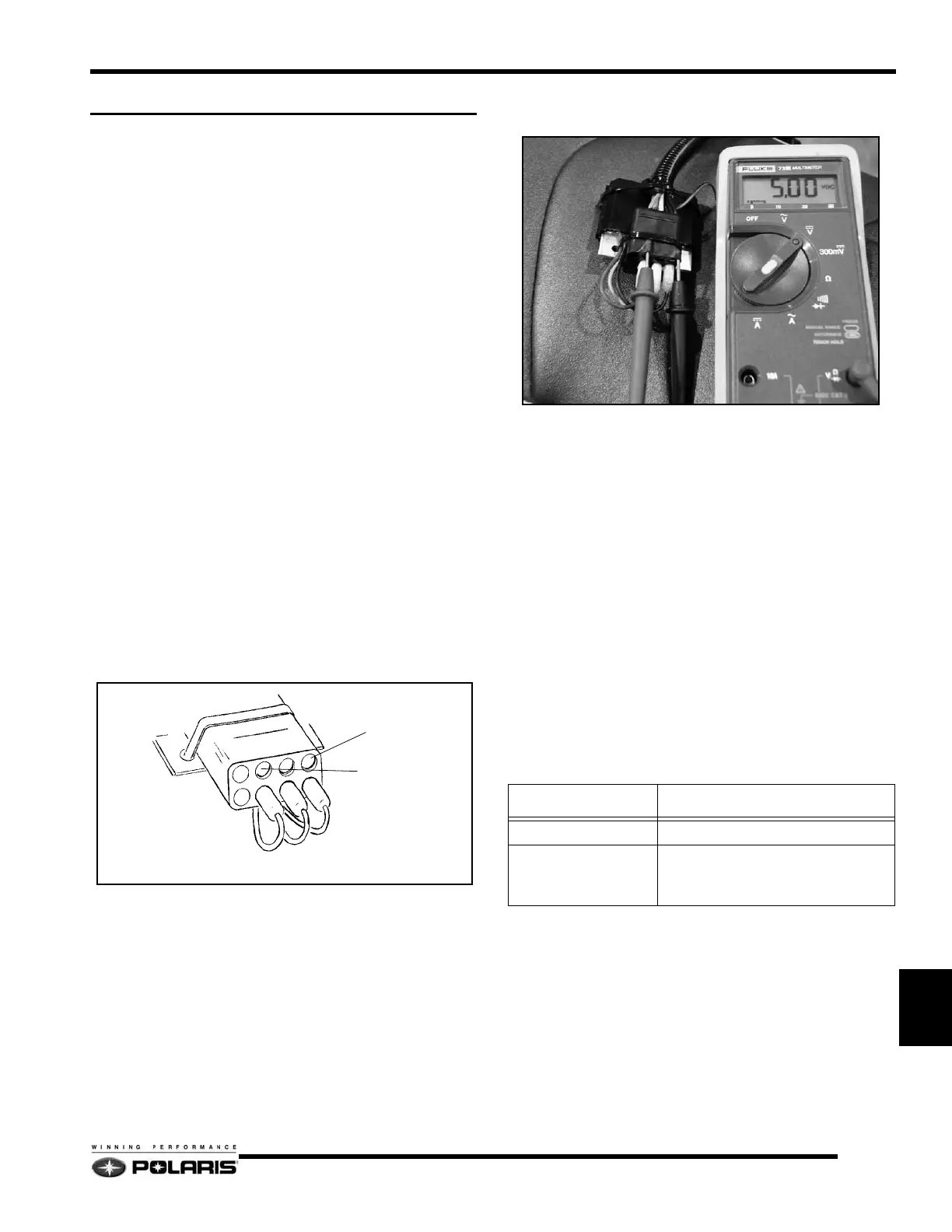
1. Set the multimeter to read Vdc.
2. Verify the 9 volt battery condition by inserting the black
multimeter probe into the black wire terminal and the red
multimeter probe into the pink wire terminal. Voltage
should read 4.99 to 5.01 Vdc. Use a new battery if voltage
is below 4.99 Vdc.
3. Connect the test tool to the TPS on the carburetor or throttle
body.
NOTE: Always disconnect the 9 volt battery when
tool is not in use.
Using the TPS Test Tool
1. Remove the wiring harness connector from the TPS.
2. Verify the throttle cable is not kinked and the throttle flipper
is closed. Disconnect the throttle cable from the throttle
flipper.
3. Connect the test tool to the TPS.
4. Insert the black multimeter probe into the black terminal
port, then insert the red multimeter probe into the yellow
terminal port.
5. Reference the specifications to determine if the TPS
requires adjustment or replacement.
6. Reconnect the throttle cable with throttle flipper.
7. To verify the TPS is sending a linear signal, slowly move
the throttle flipper from the closed to WOT position, then
back down to the closed position.
8. The voltage readings displayed on the multimeter should
rise and fall without erratically jumping from high to low.
NOTE: The multimeter display may change scales
and show O.L. momentarily when throttle flipper is
moving.
9. If the signal readings are erratic, replace the TPS sensor.
Black
Probe
Red
Probe
Red
Pink
Black
TPS Setting Specifications
ENGINES VOLTAGE SETTINGS
Carbureted Engines 4.00 +/- 0.1 Vdc @ WOT
CFI Engines
600 / 700
800
0.95 +/- 0.01 Vdc @ Idle
0.93 +/- 0.01 Vdc @ Idle

 Loading...