17
Replacing Ranging Board
1. Reconnect the following wires to the ranging board (Figure 2-7) on previous page):
• White wire to self-locking terminal J5
• Brown wire to self-locking terminal J4
• Black trnsducer lead to terminal J19 (GND)
• Black/red lead to terminal J20
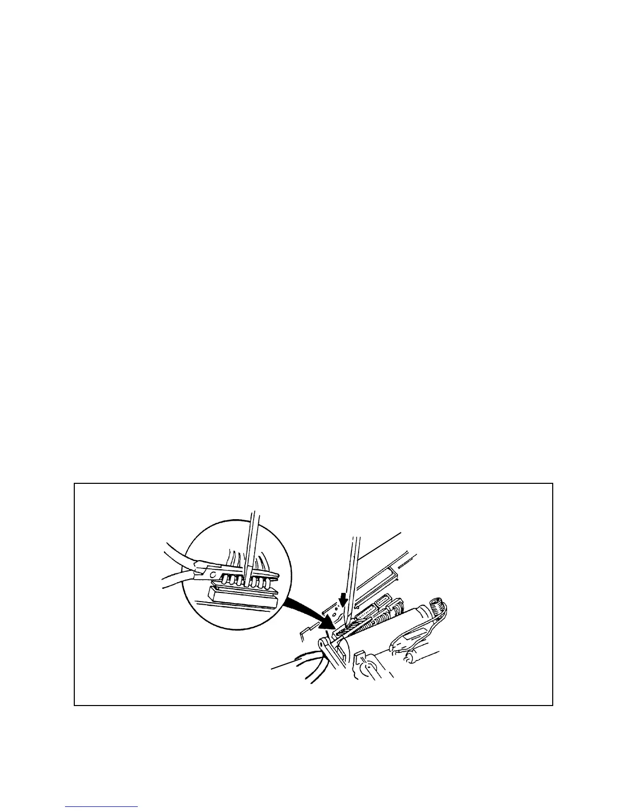
2. With needle-nose pliers, alighn the wire connector J1 (from the One Board
Strobe/Exposure Module Assembly) with the mating pin connector on the ranging
board (Figure 2-8), then press the wire connector into position with solder aide
tool 941168.
3. Using the same technique described in step 2, reconnect wire connectors J2 and J3
(from the One Board Strobe/Exposure Module Assembly) with their mating pin
connectors on the ranging board.
4. Place the ranging board in its normal position, with the projecting tabs on the main
frame in the notches at the bottom of the ranging board.
Figure 2-8. Reconnecting J1, J2 and J3 to ranging board
Solder Aide
Tool
Needle-Nose
Pliers
 Loading...