21
4. Disconnect the following wires from the One Board Strobe/Exposure Module
Assembly (Figure 2-11):
• Black wire from J26
• Red wire from J14
• Black wire from J15
• Orange wire from J16
• Green wire from J17
5. Unsolder the white wire from the trigger coil (Figure 2-11)
6. Disconnect wire connectors J7, J6, J4, and J5 from the One Board Strobe/Exposure
Module Assembly.
7. Lift the One Board Strobe/Exposure Module Assembly to access wiring connectors
J9, J10, and J11 on the ranging board.
8. Release each of the three connectors (J1, J2, J3) from the ranging board
(Figure 2-11) by grasping each connector between your thumb and index finger
and lifting one side of the connector at a time.
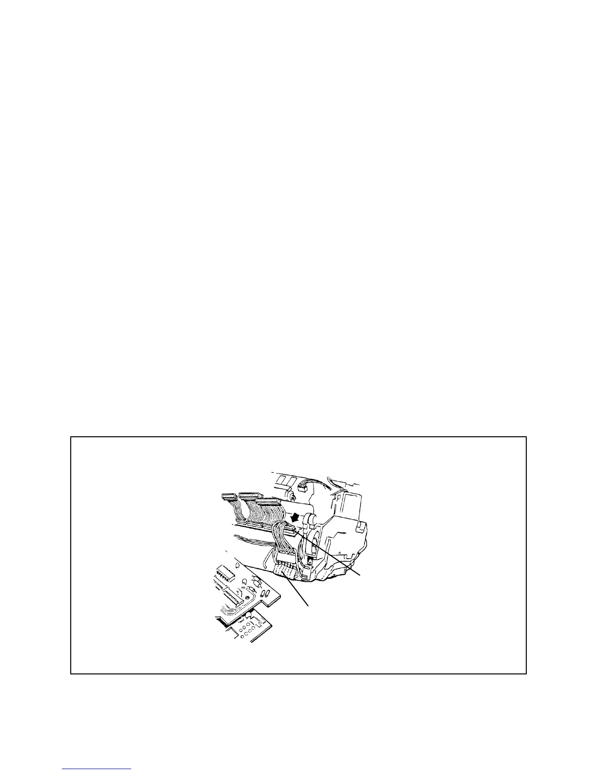
9. Release wire connector J8 (from the Wire/Motor Gear Drive Flex Assembly) from the
One Board Strobe/Exposure Module Assembly (Figure 2-12).
Figure 2-12. Removing J8 from one board strobe/exposure module
J8
Motor/Gear Drive
Flex assembly
 Loading...