THE ART OF WELDING
P6
PN-0509076 Rev. 16 41-92
1
2
1
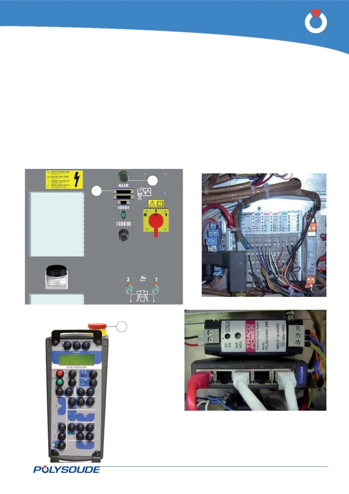
Option commands mechanised equipment4. 4. 13.
Fig. 4.18 - Power source rear connection panel
Fig. 4.19 - Modules
Fig. 4.20 - Ethernet swtich and power supply
With this option the power source operates mecha-
nised equipment type boom, positioner etc. The
power source is equipped with modules (Fig.4.19) of
an Ethernet switch and power supply (Fig. 4.20), and
is associated with an external drive.
To access the modules must remove the left side plate
of the power source. To access the Ethernet switch
and power supply must be fi led right side plate of the
power source.
The drive connects to the power source via a cable
equipped with an auxiliary connector 44–pin (0-10 V
or -10/+10 V signal, right stop and left stop, drive
connect OK, direction control, triggering the start
and stop welding cycle).
The auxiliary connector is connected to the outlet
FA 20 (Fig.4.18 - Pos. 1) on the back cover of the
power source.
The power source is equipped with an emergency
stop (Fig.4.18 - Pos. 2) that is used to connect an
emergency stop button on a bay, a desk or other
customer equipment. The remote control is also
equipped with emergency stop button (Fig.4.21 -
Pos. 1).
These emergency stops power cut stops of the entire
installation.
Fig. 4.21 - Remote control unit
with emergency stop