THE ART OF WELDING
P6
62-92 PN-0509076 Rev. 16
1
1
1
1
Maintenance and troubleshooting 6. 2.
Replacement of fuses6. 2. 1.
Warning: a blown fuse often indicates
That there is a fault. Take great Care
when switching on the machine after
a fuse has been replaced.
The FU1 delayed action fuse 4 A (Fig.6.3 – item 1) for
the supply of all auxiliary devices is situated at the
lower left side of the power source.
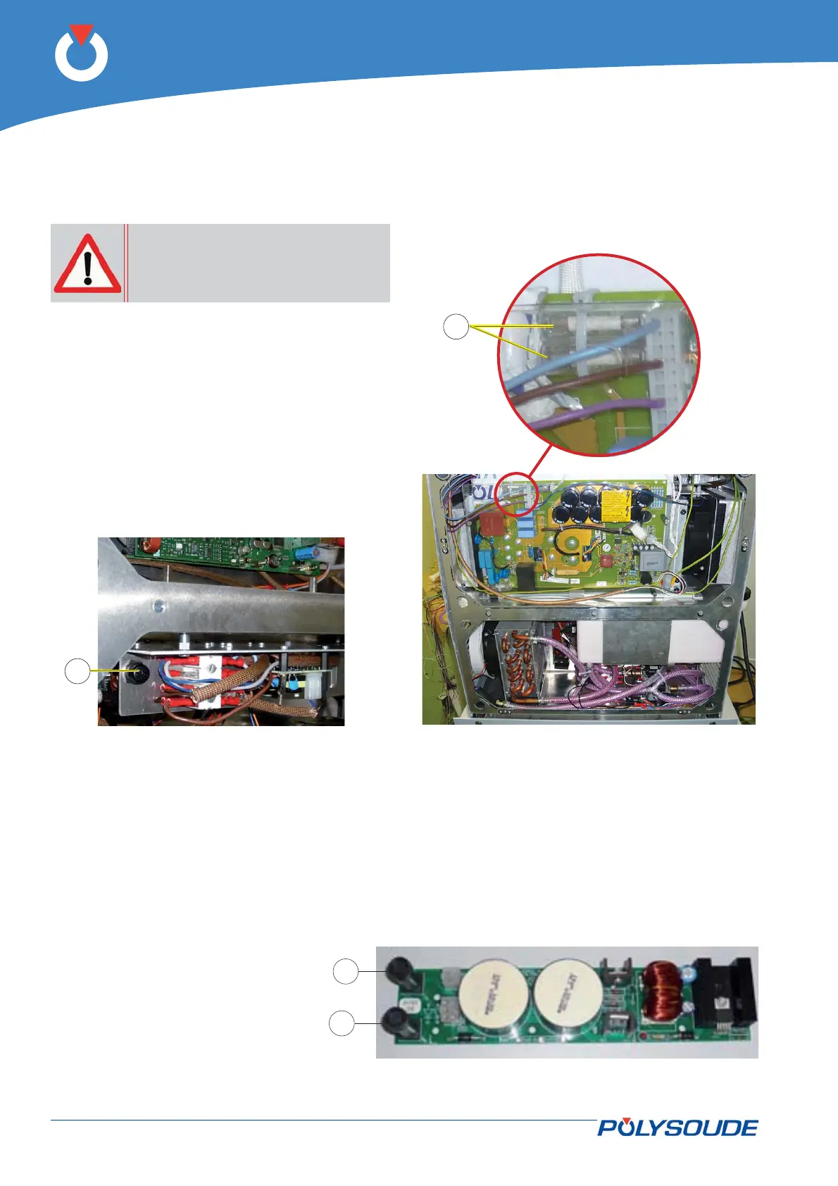
The F1 and F2 delayed action fuses 6.3 A (Fig.6.4 –
item 1) for the primary power supply of the auxiliary
transformer are situated at the upper right side of the
power source.
Fig. 6.3 - Fuse FU1 location
Fig. 6.4 - Fuses F1 & F2 location
Fuses coolant pump control 6. 2. 2.
3 A timed fuses (Fig.6.5 - item 1) coolant pump control are at the end of the module "Interface pumps / motors
chokes" reference 0028229100.
Fig. 6.5 - Interface card Pumps / motors chokes