THE ART OF WELDING
P6
PN-0509076 Rev. 16 59-92
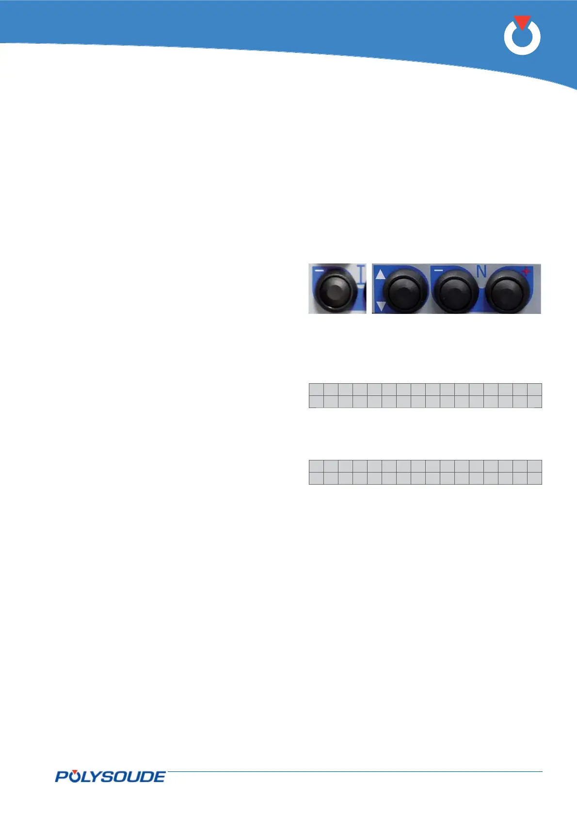
BT 6
BT 1
BT 2
BT 3
Servicing 6. 1.
Adjustments6. 1. 1.
General
The following information concerns routine checks
and adjustments to be performed periodically or as
often as necessary.
These operations are not the same as calibrations
that have to be done periodically in order to satisfy
quality system requirements, according to ISO 9000
or Quality Assurance regulations.
These calibrations must be performed usinginspec-
tion equipment which has itself been calibrated in
accordance with written procedures by personnel
appointed for that purpose.
When to adjust?
Due to the ageing of components, a drift of the
source characteristics may occur gradually. There-
fore it is recommended to check the power source
adjustments once a year.
Exchange of cards or the source
Adjustment is necessary after replacement of the
card 0028029300 or the source.
Servicing, maintenance and troubleshooting6.
Adjustment of the tachometer6. 1. 2.
If the power source is equipped with the optional
tachometer card, it is recommended to check whether
the programmed speed corresponds to the real travel
speed achieved by the rotation of the welding head.
The adaptation kit for the welding head connections
must be installed correctly. In home position a sign
should be marked as point of reference on the fi x part
of the welding head..
With the remote control pendant
Press the button BT 6 “I-” of the remote control
pendant during several seconds.
On the display of the remote control pendant
appears:
>IPAdress
Tacho
Select “Tacho” with the button BT 1.
Confi rm the selection with the button BT 3 “N+”.
On the display of the remote control pendant
appears:
Ca l i be r . Tacho
+:S t a r t . - :Qu i t
Press the button BT 3 “N+” again. The welding head
will now carry out a rotation of 360°. After the end
of the cycle, verify by means of the point of refer-
ence whether the rotation really stopped at 360°. If
the achieved result is correct, leave by pressing the
button BT 2 (N- = QUIT).
If the result is not o.k. adjust the travel speed of the
welding head with the corresponding potentiometer
(to identify the potentiometer, refer to the appropri-
ate operating manual) and repeat the procedure until
the rotation stops correctly at the point of reference.
Verify the adjustment by carrying out a weld cycle in
simulation mode.
Using the GUI software (PC or touch screen)
Using the touch screen, program a 360° rotation and
start a weld cycle in simulation mode. After the end of the
cycle, verify by means of the point of reference wheth-
er the rotation really stopped at 360°. If the achieved
result is correct the welding can be carried out.
If the result is not o.k. adjust the travel speed of the
welding head with the corresponding potentiometer
(to identify the potentiometer, refer to the appropri-
ate operating manual) and repeat the procedure until
the rotation stops correctly at the point of reference