THE ART OF WELDING
P6
42-92 PN-0509076 Rev. 16
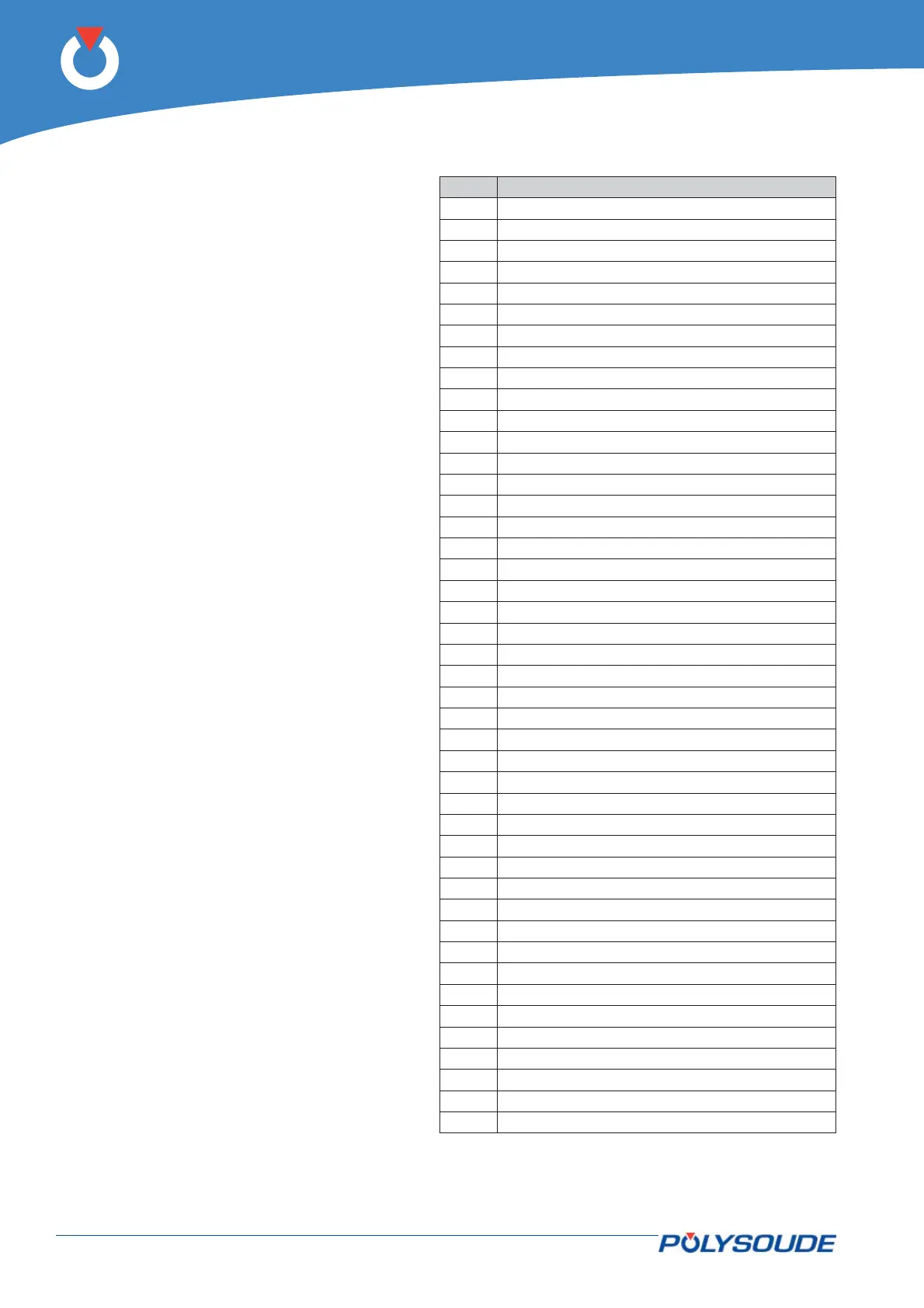
Fig. 4.22 - Connector wiring
Item Description
1 Way A encoder
2 0V encoder
30V
4 Drive connects ready
5 Order cycle stop
6 24 V max (input)
7 Reverse gear
8 24 V max (input)
9 0V motor
10 Not used (0->10V signal)
11 Not used
12 Not used
13
14
15
16 Way B encoder
17 0V encoder
18 24V output
19 Left stop
20 Order start cycle
21 Forward run
22 24 V max (input)
23 State with arc
24
25 Not used (0->10V input)
26
27
28
29
30
31 Not used
32 Not used
33 Right stop
34 Downslope cycle control
35 24 V max (input)
36 State cycle
37 Set motor 0->10V or -10V->10V
38
39
40
41
42
43
44
The rear connector 44–pin connector allows the
drive. Here the representation of the connector
with the I / O available.