THE ART OF WELDING
P6
56-92 PN-0509076 Rev. 16
BT 1
BT 2 BT 3
BT 4
BT 15
BT 5
V 4
V 3
Execution of a weld cycle5. 2.
Safety precautions5. 2. 1.
Before starting any manipulation
on the equipment please refer to
chapter 1 "Safety precautions".
Program selection5. 2. 2.
The WP and the program to be executed are selected
with BT 1, BT 2 and BT 3 on the remote control unit.
The names of the WPs and the program selected are
shown on the remote control unit display and on
the home page of the touchscreen. After 2 seconds
without operator action the WP or program is loaded
and can be used.
A long press (> 2 s) on button FA 16 will print out
the selected program.
Fig. 5.6 - “Simulation / With arc” indicator lights
Simulation5. 2. 3.
To check the selected program without affecting the
workpiece to be welded, a simulation can be start-
ed.
In this case, all the functions of the program are
carried out except those concerning the arc.
The gas commands are executed as programmed
but any fl ow rate faults are not noted. So it is possi-
ble to check the fl ow adjustment or reduce the gas
consumption during the simulation. Selection of a
simulation is made with BT 4 which illuminates V 1.
Fig. 5.5 - Command button used to select the
welding program
Weld cycle5. 2. 4.
Start of a weld cycle
A weld cycle is started by pressing BT 15 on the
remote control unit.
Fig. 5.7 - Weld cycle start push-button
Parameter modifi cations during a weld cycle
By means of the remote control unit, parame-
ter modifi cations can be easily made during a weld
cycle.
Parameters which can be modifi ed within each
sector:
The current (• I22) and/or the back ground cur-
rent (I23) in the case of pulsed current.
The rotation speed • (V32) and/or the low rota-
tion speed (V33) in the case of pulsed rotation.
The wire speed • (V42) and/or the low wire speed
(V43) in the case of pulsed wire.
The AVC (• H50) the height.
The oscillation • (T63) left edge delaying (T62)
right edge delaying (V60) the gap (A62) the
amplitude.
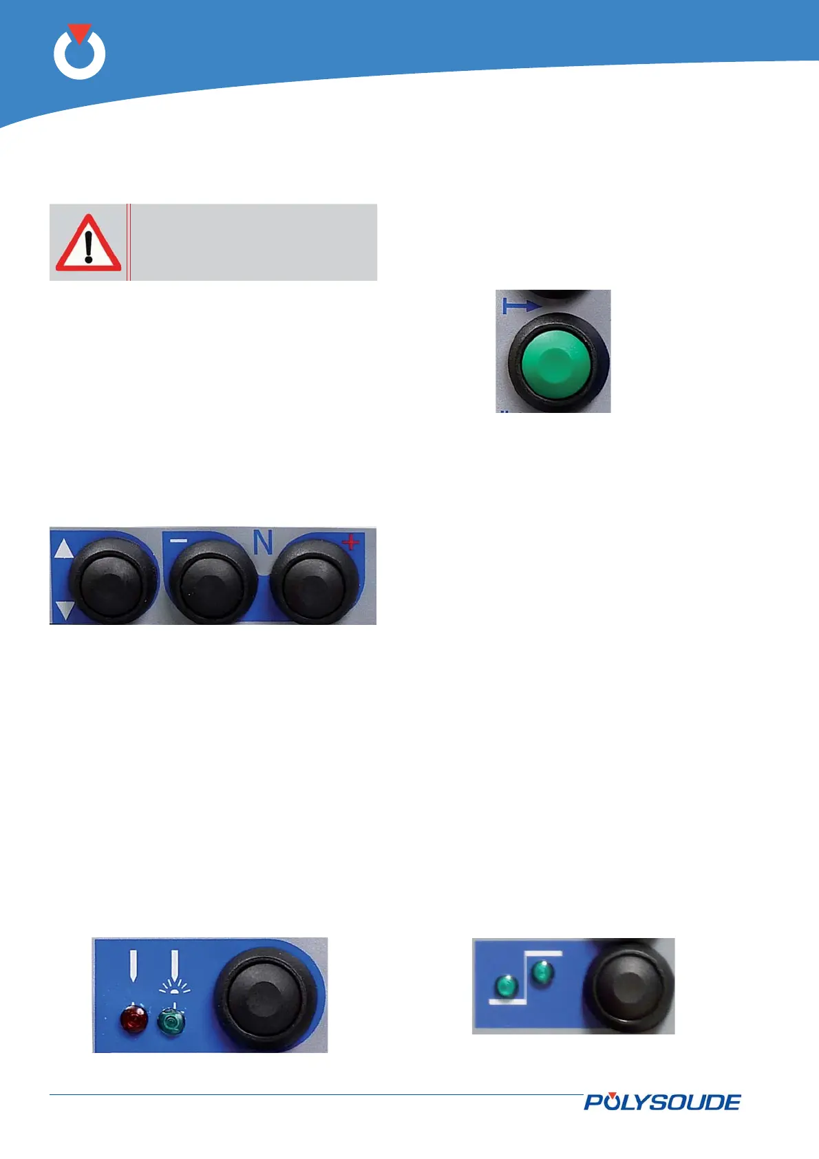
The modifi ed parameter values can be confi rmed
with BT 5 in conjunction with the 2 indicator lights
V 3 and V 4:
V 3• illuminated: Modifi cations of the low levels.
V 4• illuminated: Modifi cations of the high levels.
V 3• & V 4 illuminated: Modifi cations of the low
and of the high levels.
Fig. 5.8 - BT5 push-button