THE ART OF WELDING
P6
50-92 PN-0509076 Rev. 16
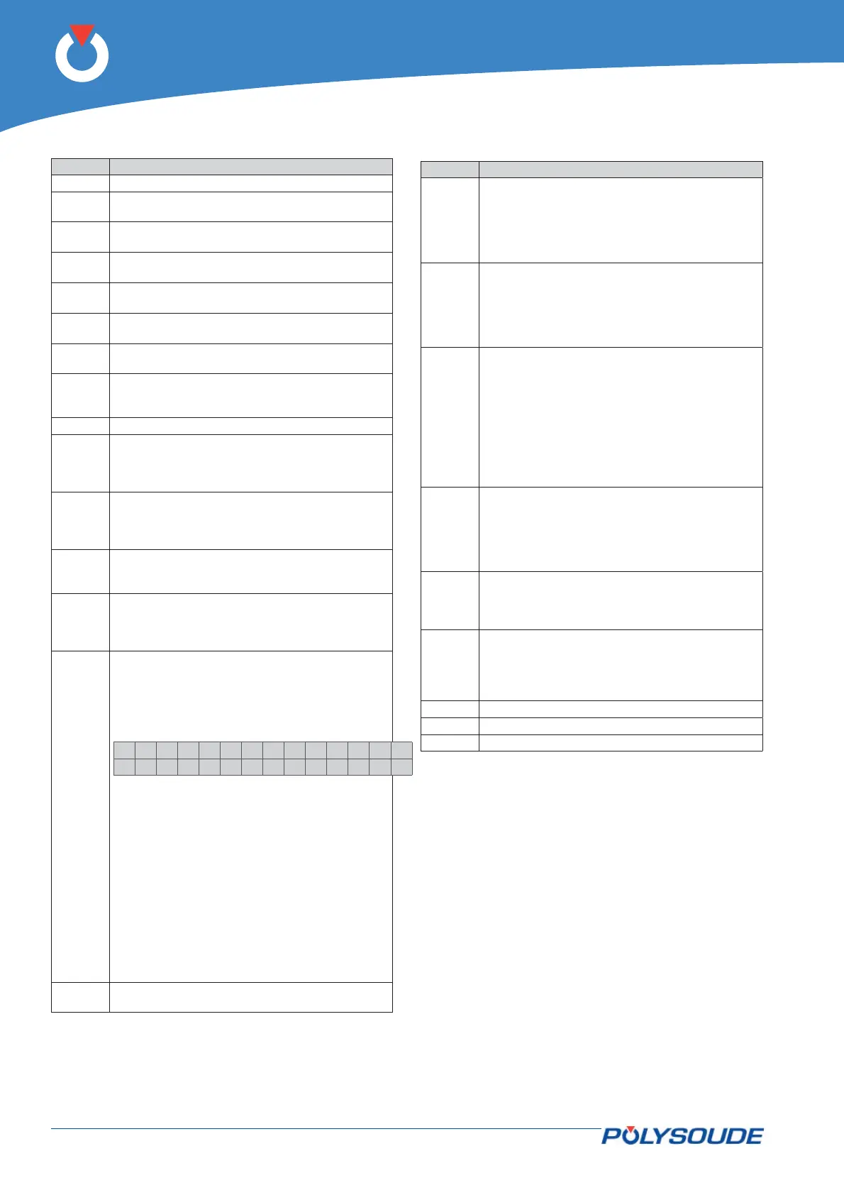
Remote control pendant 4 axis 00261491014. 5. 5.
Function of operating elements
Pos Designation
AF 1 2 line 16 character backlight display.
V 1 Red indicator illuminated: Simulation without
arc.
V 2 Green indicator illuminated: Weld mode with
arc.
V 3 Green indicator illuminated: Increment actions
on low level.
V 4 Green indicator illuminated: Increment actions
on high level.
V 3+
V 4
Green and red indicator illuminated: Increment
actions on low and high level.
V 5 Red indicator illuminated: fi ller wire operation
during weld cycle controlled by BT 10.
V 6 Green indicator illuminated: automatic fi ller
wire operation according to programmed pa-
rameters.
BT 1 Push button for line toggling on the display.
BT 2 Push button to move down in the WP or pro-
gram list or to decrease a numeric value. After
1 s of continued pushing, the automatic mode
is applied.
BT 3 Push button to move up in the WP or program
list or to increase a numeric value. After 1 s
of continued pushing, the automatic mode is
applied.
BT 4 Push button to toggle between simulation
without arc and weld mode with arc (associated
with V 1 & V 2).
BT 5 Push button to toggle between increment ac-
tions on low level, increment actions on high
level or increment actions on both levels (as-
sociated with V 3 & V 4).
BT 6
Out cycle : Press the button BT 6 “I-” of
the remote control pendant during several
seconds.
On the display of the remote control
pendant appears:
>IPAdress
Tacho
Select “IP Adress” with the button BT 1.
Confi rm the selection with the button
BT 3 “N+”.
Modifi cation of the IP address. The IP ad-
dress is in the form of four numeric blocks
that can be modifi ed by BT 2 and BT 3.
Moving from one block to another is effected
by a pulse on BT 1. Once you have reached
the last block, pressing once more on BT 1
stores the new entry in memory and termi-
nates the IP address modifi cation procedure
During a weld cycle: Decrementation of the
weld current level selected with BT 5.
BT 7 During a weld cycle: Incrementation of the weld
current level selected with BT 5.
Pos Designation
BT 8 Push button operating in two modes:
Out of cycle: Manual rotation rearwards at low
speed during 1 s, at medium speed during 2 s,
afterwards at full speed.
During a weld cycle: Decrementation of the
rotation speed level selected with BT 5.
BT 9 Push button operating in two modes:
Out of cycle: Manual rotation forwards at low
speed during 1 s, at medium speed during 2 s,
afterwards at full speed.
During a weld cycle: Incrementation of the
rotation speed level selected with BT 5.
BT 10 Push button operating in two modes:
Out of cycle in automatic mode (V 6 illumi-
nated): Manual wire feeding forwards at low
speed during 1 s, at medium speed during 2 s,
afterwards at full speed.
Out of cycle in manual mode (V 5 illuminated):
The fi rst touch starts wire feeding at high
speed, the second touch stops it.
During a weld cycle: Incrementation of the wire
feeding speed level selected with BT 5.
BT 11 Push button operating in two modes:
Out of cycle: Manual wire feeding rearwards at
low speed during 1 s, at medium speed during
2 s, afterwards at full speed.
During a weld cycle: Decrementation of the
wire feeding speed level selected with BT 5.
BT 12 Push button to toggle between the automatic
wire feeding mode (indicator V 6 illuminated)
or the manual wire feeding mode (indicator V 5
illuminated).
BT 13 Push button operating in two modes:
Out of cycle: coolant pump, gas 1 and gas 2
commands.
During a weld cycle: Manual cycle stop with
downslope.
BT 14
Push button “Start cycle with restart”.
BT 15 Push button "Start cycle".
BT 16 Push button "Stop cycle immediately".