DESCRIPTION:
DATE:
DRAWING NO:
1of17
SHEET:
REVI SION:
N
NOTE:
Callout letter
and
map to drawing #164201300---6
,,,
013004
A
B
C
D
164201300---1
POWER WIRING INSTALLATION NOTES
A --- 2
Powerware 9330 (10 kVA--40 kVA) Installation and Operation
164201300 Rev . N 013004
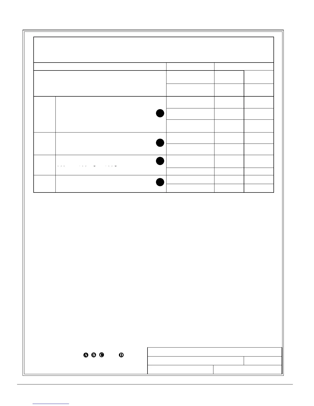
Table A. INPUT/OUTPUT Ratings & External Wiring Requirements for
Po werw are 9330---20/10
(Without Options Cabinet)
Ratings
Units Rating 50/60 Hz
Basic unit ratings at
0.7 lagging PF load
KVA
KW
10
7
10
7
INPUT/OUTPUT
VOLTAGE
208 220
CIn
ut to UPS Rectifier
0.95min.PF
C
.
.
3,1gnd
mps* 28 27
INPUT
,
Minimum conductor size (number per )
AWG or kcmil(ea) 8(1) 8(1)
*(Maximum amps includes full load current plus
battery recharge current)
C
AC Input to Module Bypass (UPS Bypass)
Full Loa
Cu
en
3
1
Neut
al
1
Amps
27.8 26.3
INPUT
,
,
Minimum conductor size (number per )
AWG or kcmil(ea) 8(1) 8(1)
DC
DC Input from External Battery Source to UPS
(1) positive, (1) negative, (1) gnd
VDC (Nominal)
Amps
288
26
288
26
INPUT
Minimum conductor size (number per pole) (See note 8)
AWG or kcmil(ea) 8(1) 8(1)
C
AC Output to Critical Load
Amps 27.8 26.3
OUTPUT
ull Loa
Cu
e
t3,
1) Neut
al,
1) g
Minimum conductor size (number per )
AWG or kcmil(ea) 8(1) 8(1)
Read and understand the following notes while planning your installation:
1. Refer to national and local electrical codes for acceptable external wiring practices.
2. The bypass feed into this equipment utilizes four wires. The rectifier feed into this
equipment utilizes three wires. However, the phases must be symmetrical about ground
(i.e., from a Wye source) for proper equipment operation. Failure to follow these
instructions will void the product warranty.
3. Material and labor for external wiring requirements are to be provided by designated
personnel.
4. For external wiring, use 90°C copper wire. See the appropriate column in Tables A
through M.
5. Wire ampacities are chosen from Table 310---16 of the NEC.
6. A bypass neutral feeder must be supplied.
7. Refer to Section I of this manual for installation Instructions.
8. UPS systems not using an external battery source are supplied with internal batteries
prewired to the UPS at the factory. External Line-up and Match Battery cabinets are
provided with with quick disconnect cables for connection to the UPS. No external wiring
is required for Line-up and Match battery cabinets. All products can be connected to an
external battery source through the DC connections terminal block. An external DC
ground is established through the grounding terminal in the bottom of the cabinet.