13--2
Powerware 9330 (10 kVA--40 kVA) Installation and Operation
164201300 Rev . N 013004
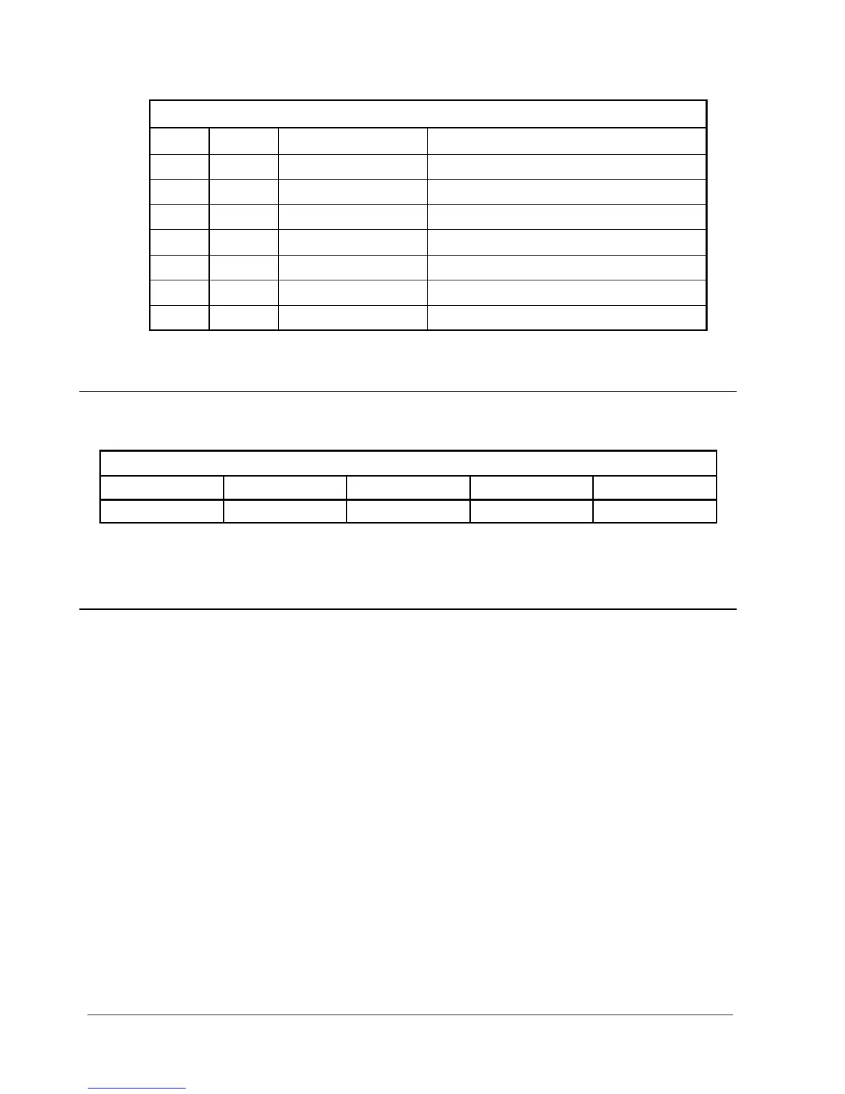
Ta b l e 1 3 --- 1 . P i n A s s i g n m e n t s f o r S e r i a l P o r t ( D B --- 9 )
Pin # Symbol Description Comments
2 TXD Transmit Data Input to UPS
3 RXD Receive Data Output from UPS
4 DSR Data Set Ready
5 RTN Return
6 DTR Data Terminal Ready
7 CTS Clear to Send
8 RTS Ready to Send
13.3 Configuring the Serial Port
Table 13---2 lists the default configuration settings for the serial communications
port.
Table 13---2. Serial Communications Port
Baud Data Bits Stop Bit Parity Handshaking
9600 8 1 No Disabled
The serial port is pre-configured and can not be changed.
13.4 X-Slot Cards
The Powerware 9330 contains a factory-installed X-Slot communication bay (refer to
Appendix A, Drawings 164201300---8 or 164201300---9 for bay location), and is
compatible with the following optional cards (see Figure 13---2):
• Modbus Card --- provides direct integration of UPS information (meters and
status) to a building management system (BMS) using the Modbus RTU
protocol.
• ConnectUPS - X Web/SNMP Card --- provides remote monitoring through a Web
browser interface, e-mail, and a network management system (NMS) using
SNMP; connects to a twisted-pair Ethernet (10/100BaseT) network.
• Modem Card --- provides “out-of-band” remote notification and monitoring
using modem communication directly to cell phones and pagers.
• Relay Interface Card (AS-400) --- provides a voltage-free ”true relay” interface
for IBM AS/400 computers, other relay connected computers, and industrial
applications.
t