7-- 12
Powerware 9330 (10 kVA--40 kVA) Installation and Operation
164201300 Rev . N 013004
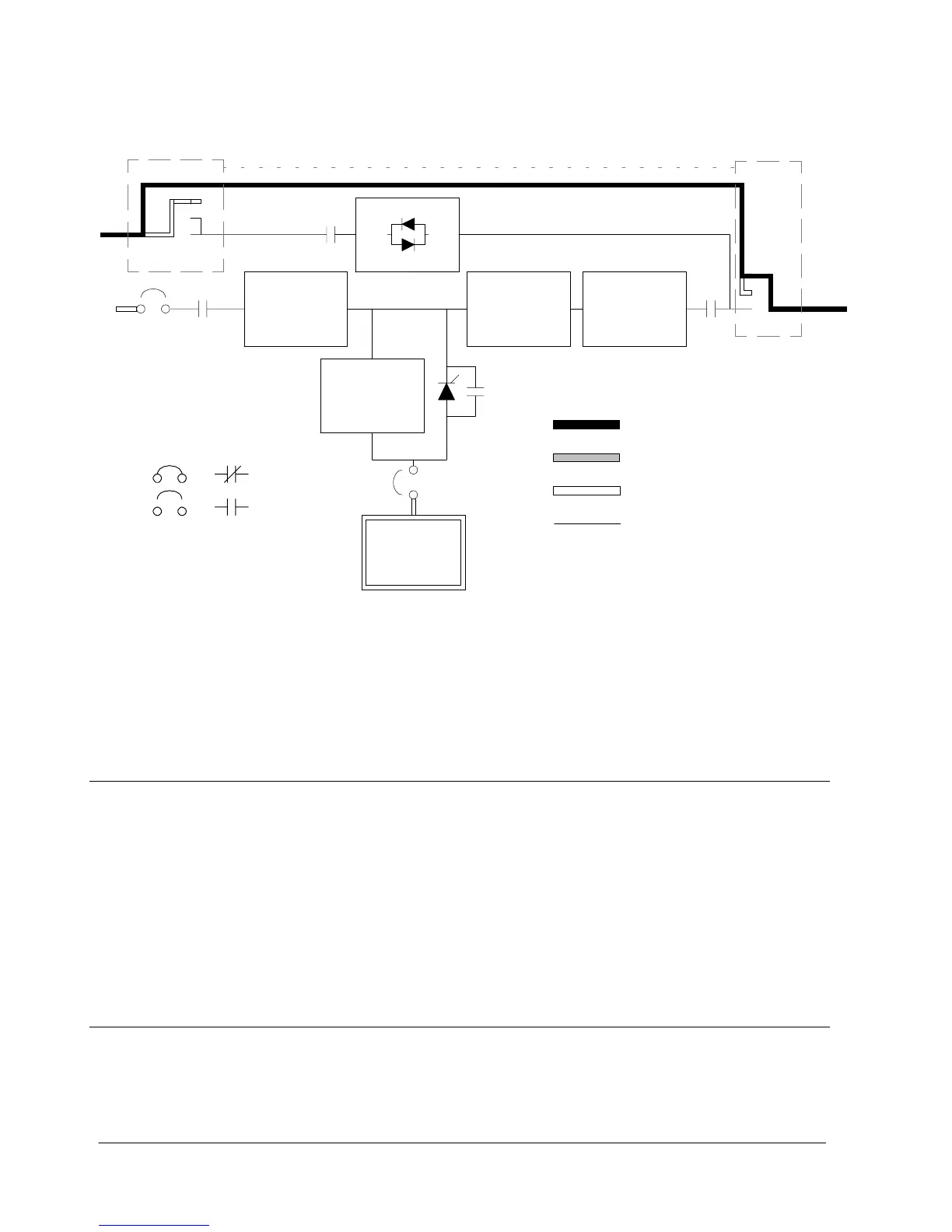
CB1
CB2
K1
K5
K3
K2
Open
Closed
Breakers
Contactors
Main Power Flow
Energized
De--Energized
Trickle Current
RECTIFIER
STATIC
SWITCH
BOOST
CONVERTER
INVERTER
MAINTENANCE BYPASS MODE
CHARGER
BATTERY
MAINTENANCE
BYPASS SWITCH
MAINTENANCE
BYPASS SWITCH
Figure 7---7. Path of Current Through the UPS in Maintenance Bypass Mode
7.3 Functional Description
The UPS is a true online unit with a series power train. An uncontrolled rectifier
feeds a boost converter, which in turn powers the inverter. The bypass utilizes a
static switch and a maintenance bypass switch is internal to the unit. The unit input
is 3---wire in (plus ground) at the rectifier and 4---wire in (plus ground) at the
bypass, and 4 wire output. The unit does not incorporate any galvanic isolation,
input to output. The battery string comprises 144 cells (288 volts nominal) and is
charged via a buck or boost converter powered from the raw DC IN from the input
rectifier.
7.3.1 Input Rectifier
The Input Rectifier is a full wave bridge uncontrolled rectifier, which produces an
unregulated DC IN Bus. The raw DC at this point will be approximately 290 VDC. A
precharge system precharges the DC IN Bus prior to the input contactor being
closed.