Prontonet User’s Manual v410 15
II.3.4 GPIO Port
WARNING
GPIO has been modified in ProntoNet with serial number 8938/00250 or higher.
Since this production, the GPIO is provided with 7 inputs and 7 outputs.
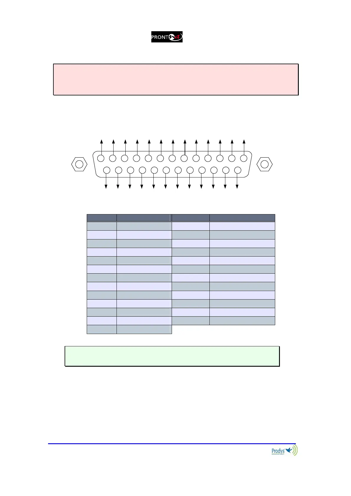
A subD 25 pin socket provides a general purpose connection with 7 inputs and 7
outputs. The connections must be wired according to the following diagram:
12345
15
9 678
1617181920
10111213
25 24 23 22 21 14
NC
NC
NC
NC
OUT1
OUT3
OUT5
OUT7
NC
OUT2
OUT4
OUT6
GND
VCC
NC
IN2
IN4
IN6
NC
NC
IN1
GND
IN3
IN5
IN7
Pin Function Pin Function
1
+5VDC 14 IN 7
2
IN 6 15 IN 5
3
IN 4 16 IN 3
4
IN 2 17 IN 1
5
NC 18 NC
6
NC 19 NC
7
GND 20 GND
8
OUT 7 21 OUT 6
9
OUT 5 22 OUT 4
10
OUT 3 23 OUT 2
11
OUT 1 24 NC
12
NC 25 NC
13
NC
Pin 1 is connected to +5 volts. If you need it , run this power supply through
your device with a resistor in series to limit the maximum current to 300 mA.
II.3.4.1. Inputs
The inputs are active for grounding (active low).