MVI56-PDPMV1 ♦ ControlLogix Platform Configuring the MVI56-PDPMV1 Module
PROFIBUS DPV1 Master User Manual
Page 87 of 251 ProSoft Technology, Inc.
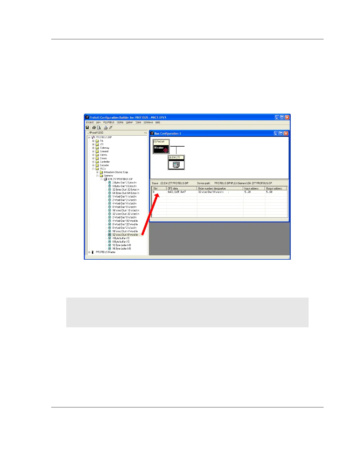
5 Drag the input and output parameters to the Slot Location Grid (Subscriber
List) below the Bus Configuration window. This view displays the slot number,
configuration data, and starting input and output addresses. The MVI56-
PDPMV1 Master uses this information to identify and communicate with
individual slaves on the network.
For this example, we will configure thirty-two (32) words of output and eight
(8) words of input. These input and output words are assigned to addresses
within the MVI56-PDPMV1 module's internal database.
For each new slave added to the PROFIBUS network, PCB automatically
converts the input/output byte addresses to word input/output addresses for
the tag database in the processor.
Tip: To make it easier to view the data from individual slaves, give each slave a meaningful name,
and place each slave's I/O areas in contiguous blocks. Use thePrinting the Processor Network
Memory Map (page 100) as an aid to cross-referencing the slave I/O data in RSLogix 5000.