5-2
ROTALIGN 01.2000
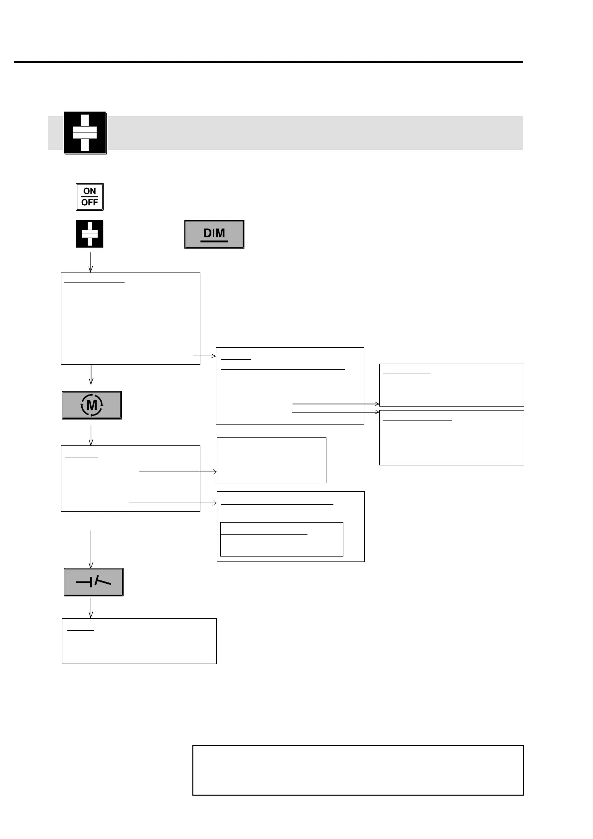
Vertical machine alignment flow chart
Vertical machine alignment flow chart
Edit dimensions (page 5-5)
NEW MACH
NUMBER BOLTS
EDIT:
Bolt distance
Flange diameter
Coupling center to receiver
CIRCLE/SQUARE
OPTION (nonsymmetrical setup) :
To review
dimensions
later press:
OPTION (page 5-11)
Edit nonsymmetrical dimensions
NORMAL ORDER
(clear and return to symmetrical)
EDIT (X-axis, Y-axis, etc.)
ADJUST CENTER:
EDIT BOLTS:
Edit bolt positions
Up, Down (select bolt from list)
EDIT X-POS, EDIT Y-POS (move bolt)
DELETE (delete bolt)
OK returns to previous menu
Move center
Up, Down, Left, Right
STEP SIZE: small, med., large, XL
OK returns to previous menu
Results (page 5-9)
SAVE (page 3-6)
+/-, -/+, 0/+ (+ve/-ve shim calculations)
MOVE (press START, then STOP)
Measure (page 5-6)
TABLE (page 4-48)
XY VIEW (page 4-43)
Arrow selects point
CLR key deactivates selected point
MEAS. MODE:
Vertical and horizontal shafts:
Measure at 1, 2, 3, 4, 5, 6, 7, 8 (5-6)
Horizontal shafts only:
Multipoint (4-36)
Continuous Sweep (4-34)
Range extend (4-46)
Curve fit (4-45)
Trace (4-27)
Average (page 4-44)
Certain functions and options are available in both horizontal and
vertical alignment modes. Where necessary in this chapter, cross-
references are provided to the relevant sections of Chapter 4.
F
Note
 Loading...
