5-3
ROTALIGN 01.2000
Vertical machine alignment
7
5
3
1
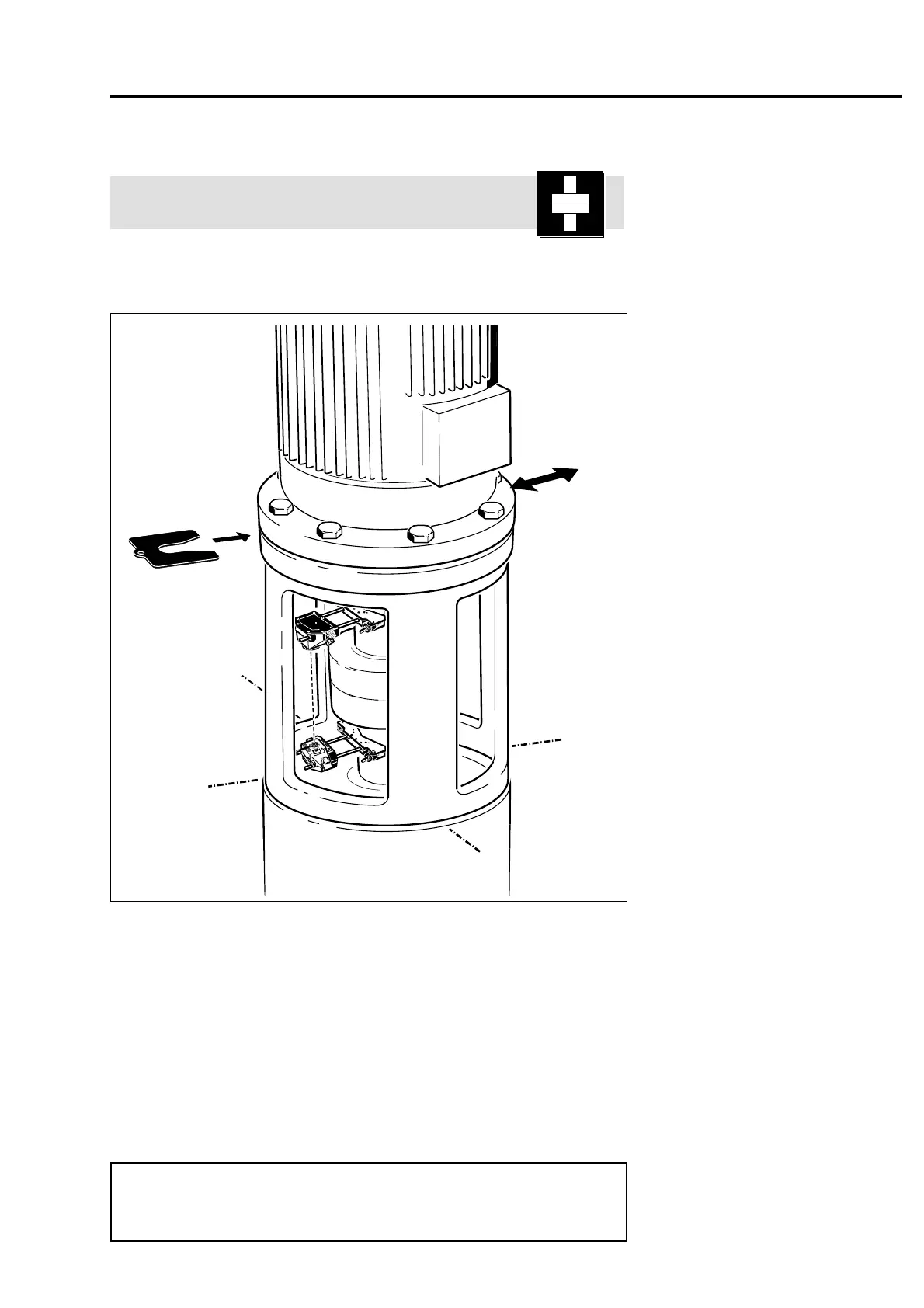
Vertical machine alignment
Vertical machine arrangements typically comprise one machine
mounted on top of another and are secured with a bolt flange as
shown below:
Offset
adjustment
(in X and Y
directions)
Angular adjustment
with shims around
the flange
The ROTALIGN laser and receiver are mounted on either side of the
coupling as for coupled horizontal machines, with the laser below
and the receiver above. Measurements are then made at a series of
90° or 45° rotational positions.
Based on these measurements and the flange shape and size, the
computer calculates the offset correction. Alignment is achieved by
inserting shims of thickness determined by the computer between the
flanges at each bolt.
The vertical alignment procedure is described in detail on the
following pages.
This section of the program also includes an option for aligning
horizontal machine arrangements connected with bolt flanges.
Turn to page 5-13 for more information.
F
Note
 Loading...
