4-23
ROTALIGN 01.2000
Horizontal machine alignment - laser beam adjustment
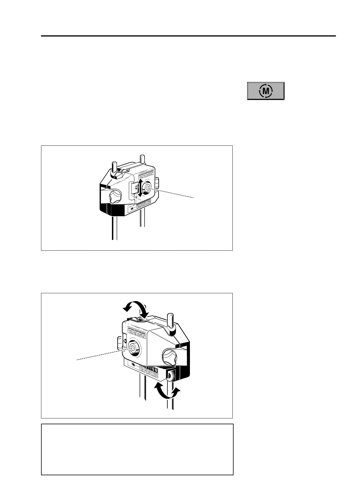
Vertical control
Horizontal control
6. Laser beam adjustment
Press the "M" key to start the measurement process. When first
mounted, the laser and receiver may be misadjusted. The laser and
receiver must then be adjusted to direct the laser beam into the
middle of the receiver housing aperture. Adjust the beam as follows:
1. Remove the cap from the laser and flip the laser switch upwards
as shown below. Do not look into the laser beam aperture.
2. With the receiver cap still mounted, adjust the height of the laser
and/or receiver to bring the laser beam level with the center of
the receiver aperture. Fine adjustment can be made by turning
the thumbwheel on top of the laser housing:
If, approximately 10 seconds after pressing the "M" key or entering
"Soft Foot" mode, the ROTALIGN fails to establish contact with the
sensor, the "SENSOR ???" message is displayed on the screen. The
message is also displayed if the receiver cable is disconnected while
ROTALIGN is in XY, Move or Soft Foot modes. Check that both
ends of the cable are properly detected.
F
Note
 Loading...
