4-25
ROTALIGN 01.2000
Horizontal machine alignment - laser beam adjustment
5. Remove the cap or beam tube from the receiver. The computer
display should resemble that pictured below.
Details of these softkeys on page 4-28
CENTERED!
Full description of XY View on page 4-
43
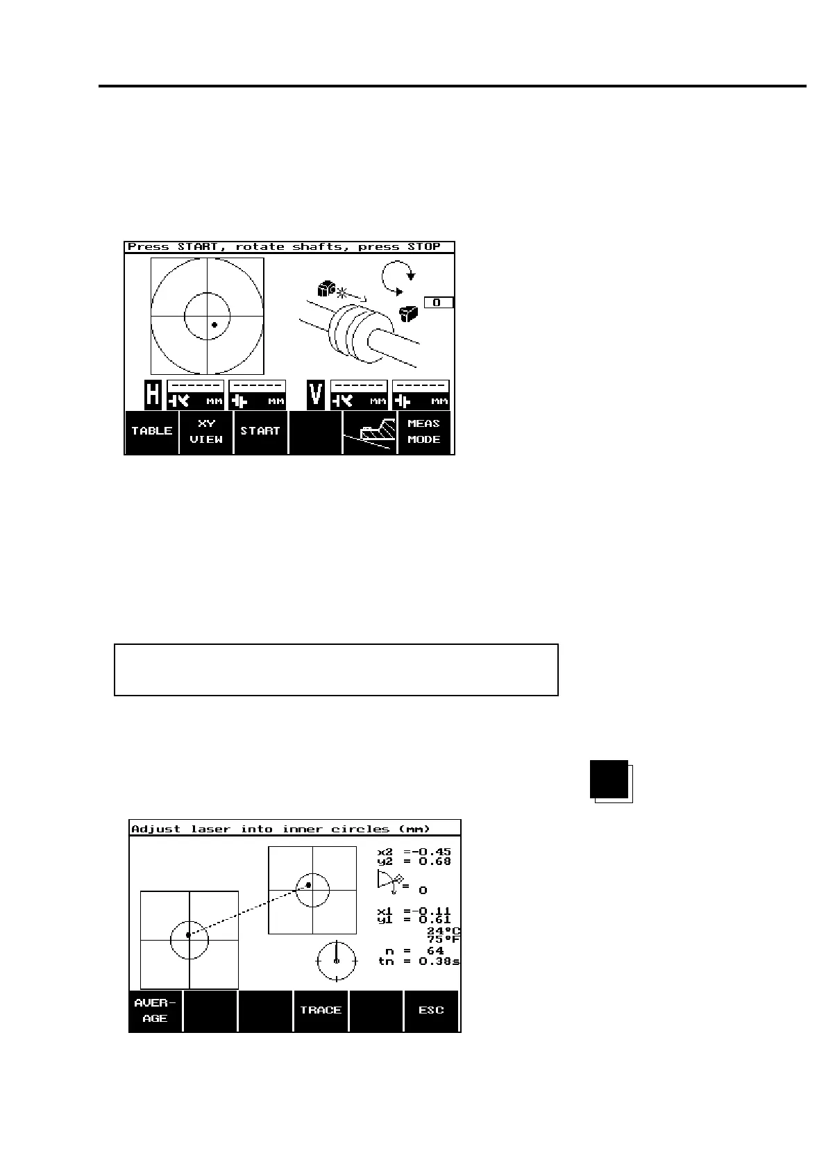
The target diagram in the left portion of the display represents
the FRONT position detector within the receiver (there are two
detectors, see page 2-15). The current beam position is shown as
a dot on this target diagram which should fall within the inner
circle. If not, use the laser thumbwheels to bring the dot into the
inner circle. (Q
UICK CHECK, page 4-3 shows points for both
detectors simultaneously.)
Make sure that the receiver lens is clean! Otherwise measure-
ment accuracy may be reduced!
6. As explained on the previous page, the beam should not only be
centered, but also reasonably perpendicular, i.e. straight-on (see
discussion on following page). To check this, centration must be
seen in both position detectors. Press the softkey marked XY
VIEW:
CENTERED!
TRACE
F
Note
XY
VIEW
 Loading...
