42.00.004
42.00.047
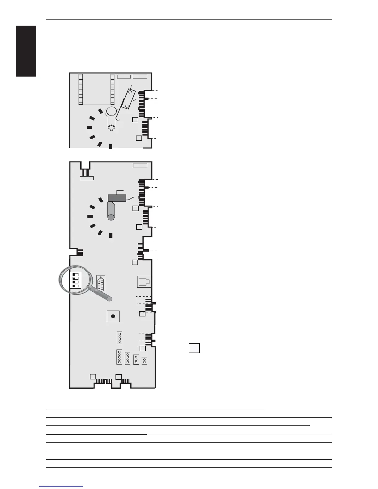
X2 B3 Core temperature
X3 B1 Interior cabinet
X4 B2 Quenching / Steam control
X6 B5 Steam generator
X7 ON - OFF switch
X8 Buzzer
X12 Level electrode
X 16 power supply from transformer (42.00.047)
X18 SC - pump
X19 Solenoid valves
X20 Energy optimising / Sicotronic
X23 Vent hood (signal door open / closed)
X24 SSR
X26 SSR pulsing (USA version only)
X27 Door contact switch
X30 Serial interface (RS232)
X31 BUS interface
X32 Timer / Core Temp. Potentiometer
X50 external EEPROM
X63 Not used
Counting sequence
Notes: Since February 2006 PCB 42.00.004 is replaced by 42.00.047.
(Conversion kit: 87.00.139, pls. see Technical info 04-06)
The transformer on the new PCB 42.00.047 is no more existing and replaced by
external transformer 40.00.227
CM PCB (42.00.004) from 04-2004
1
CM PCB (42.00.047) from 02-2006 (without transformer)
Temperature
potentiometer