-44-
S
S
C
C
X 7X 8
X 1
X 51
X 54
X 53
X 09
X 10
X 5X 2X 6X 4
X 50
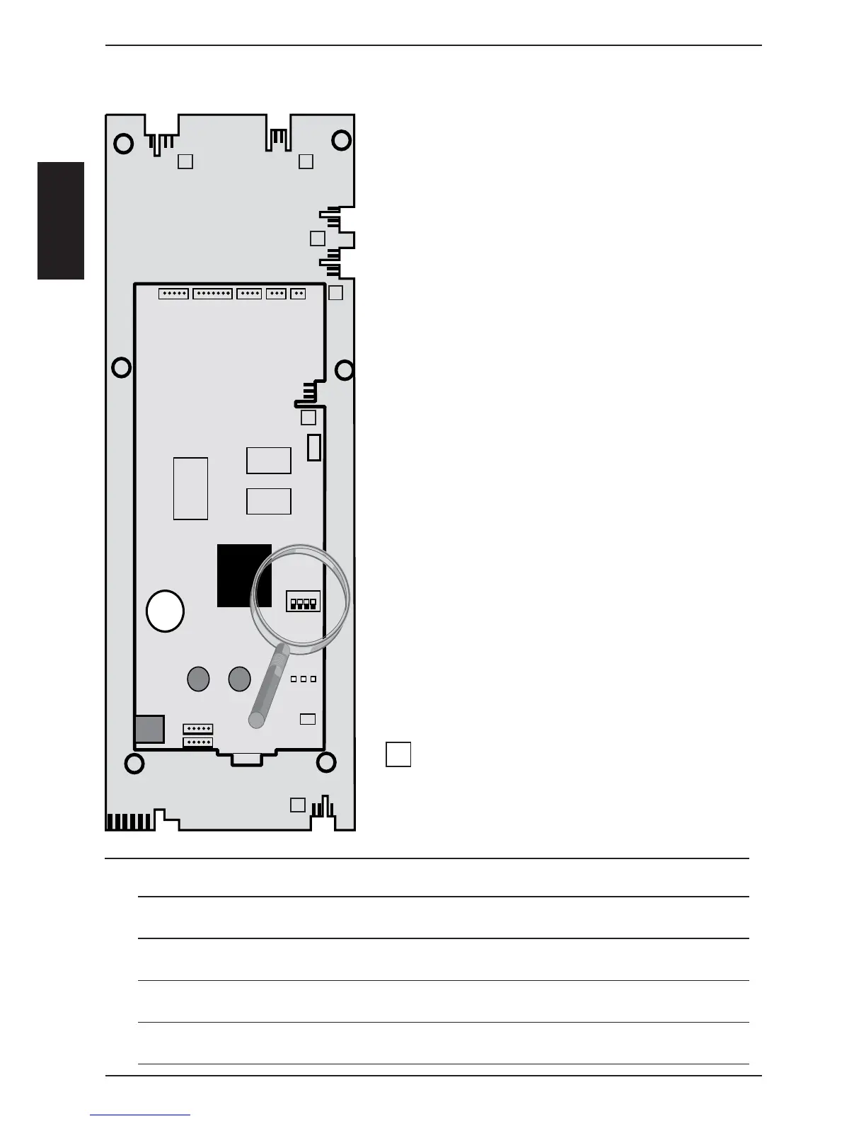
A2 SCC pcb
A3 Add On pcb
X 52
X 2
3V
ON
LED
1 2 3
X 3
RS 232
Battery
X 12
X 11
X7 200 - 240V input to I/0 Switch
X8 Buzzer
X12 Level electrode
X11 Humidity fl ap motor / Micro switch
Add on X1 P1 pressure sensor
Add on X2 B6-11 thermocouples
core temperature
Add on X3 B1 thermocouple interior cabinet
Add on X4 B2 thermocouple quenching
Add on X5 B4 thermocouple humidity
Add on X6 B5 thermocouple steam generator
Add on X50 External EEPROM
Add on X51 BUS interface
and power supply for cpu from I/O pcb
Add on X52 RS232 interface
Add on X53 USB interface (only until November 2005)
Add on X54 USB interface
Add on X09 Central dial
X10 Power suply for display 2,5 - 0 - 2,5V
(X10 indicated as X1 on pcb layout)
X2 Free
Counting sequence
Note: LED code: SCC PCB
Green LED on - ok;
Red LED blinks 1x during re-booting when switching on - ok
Green LED - off: Bus cable defective; CPU defective; I/O pcb or transformer defective
Red LED on: CPU defective
Red LED doesn‘t blink during re-booting when switching on - CPU defective
SCC Operator pcb (42.00.002)
1
1
1
1
11
1