-25-
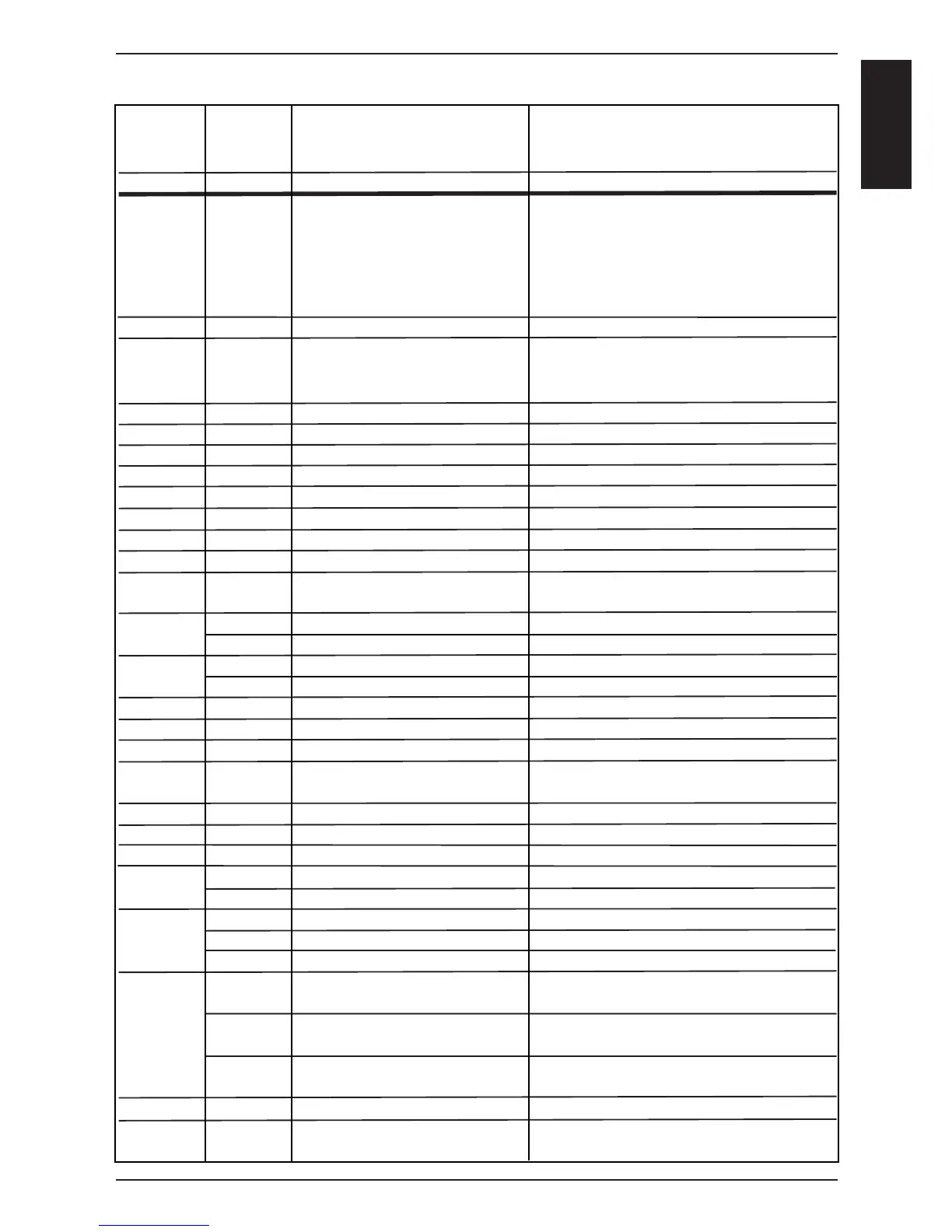
S
C
M
Int. cab.
display
H2o
CHnG
Timer
display
E1
E2
E3
E4
E5
E6
E7
E8
E9
E10
E11
E12
E 12
E13
E14
E15
E16
E17
E18
E19
E20
E21
E22
E23
E24
Timer
display
OPEn
PoL
Int. cab.
display
(E -press
core temp.
key)
1 St
1 Co
2 St
2 Co
1_
2_
1xx
2xx
3xx
1xx
2xx
3xx
Failure explanation
H2O open
Change Polarity
Part concerned
external EEPROM
Timeout of external
power optimising system
(Sicotronic)
B1 Interior cabinet sensor
B2 Quenching sensor
B3 Core sensor
B5 Sensor steam generator
Thermocouple on PCB
Poti interior cabinet
Poti timer/core temperature
External EEPROM
Mode switch
Fan motor 1 (bottom)
Fan motor 1 (bottom)
Fan motor 2 (top)
Fan motor 2 (top)
M4 SC-pump
Solenoid valve fi lling Y1
PCB temperature
Steam generator
Steam generator
Interior cabinet temp.
free
Ignition box 1
Ignition box 2
Ignition box 1 Steam
Ignition box 1 Hot air
Ignition box 2 Hot air
Ignition box 1 Steam
Ignition box 1 Hot air
Ignition box 2 Hot air
free
EEPROM
Description
Lack of water / open water tap
Phase / Neutral (only gas units)
Description
Not initialised
Heating blocked by the extern. energy-
optimising system for longer 2 min.
Sensor broken
Sensor broken
Sensor broken
Sensor broken
Sensor broken
Defective
Defective
Defective
After 5 sec switching on the unit, a
cooking mode couldn‘t be identifi ed
St = Status (probably Motor defect)
Co = Communication,(Bus failure)
St = Status (probably Motor defect)
Co = Communication,(Bus failure)
Mal function
Mal function
above 85°C (185°F)
Temperature B5 above
180°C (356°F)
Temperature B5 below -5°C (23°F)
Temperature B1 above 340°C (644°F)
Ignition box does not reply, Bus failure
Ignition box does not reply, Bus failure
Ignition box defective (change box)
Ignition box defective (change box)
Ignition box defective (change box)
Testing of ignition and monitoring
necessary
Testing of ignition and monitoring
necessary
Testing of ignition and monitoring
necessary
Actual data structure of the EEPROM
does not match with the software; flash
pcb first
Failure Codes CM from 04-2004