Switch on unit
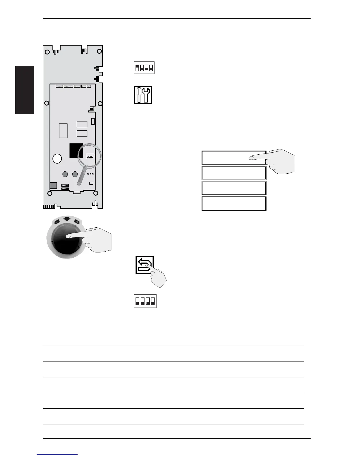
Set DIP 1 on operator PCB to „“ON““ position
Press service key
On the displays the following available
Service - modules will be shown
Window 1 Diagnostic
Window 2 Running Times
Window 3 Basic Settings
Window 4 Function Test
Activate selected service module by push on display or push
on central dial
Deactivate selected service module
by pushing on “return“ symbol
Set DIP 1 on operator PCB to “OFF“ position
to deactivate Service level
Starting with software version 01-07-02 gas related
information is not shown on electric units!
Service level SCC
X 7X 8
X 1
X 51
X 54
X 53
X 09
X 10
X 5X 2X 6X 4
X 50
A2 SCC pcb
A3 Add On pcb
X 52
X 2
3V
ON
LED
1 2 3
X 3
RS 232
Battery
X 12
X 11
A)
B)
C)
D)
E)
F)
G)
1
2
3
4
on
1
2
3
4
on
Notes: