-45-
S
S
C
C
UltraventVent .
230V
input
Energy optimising
Sicotronic
Y1 fi lling
Y2 quenching
Y3 moistening
SC pump
CleanJet pump
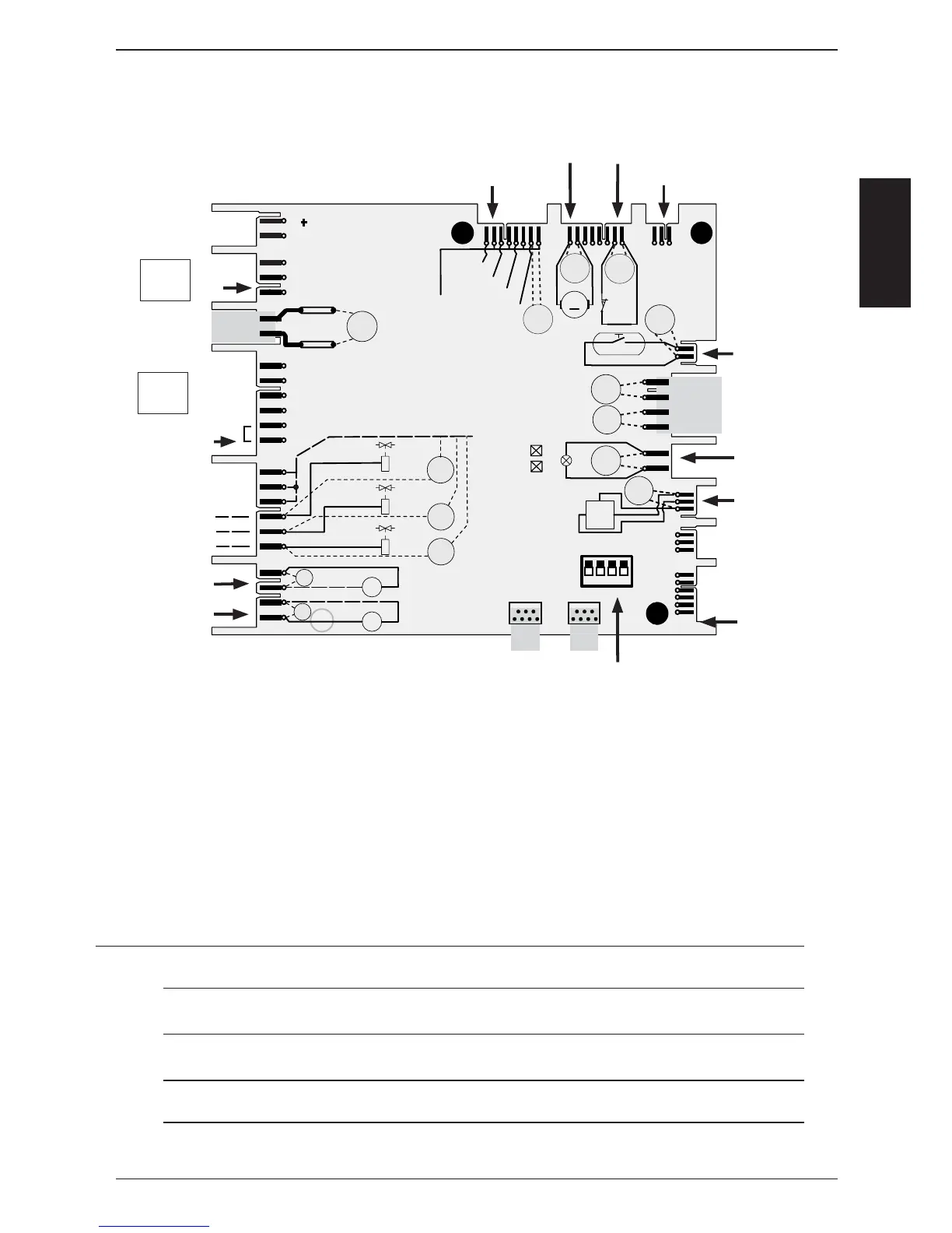
Measuring points I/O PCB SCC (40.00.049)
Wires of pcb edge connectors are pointing to component side of pcb!
Motor drain valve Micro switch drain valve
12 V DC SSR
SSR puls (USA version)
all DIP must be OFF
S3
T1
K1:L1
F2: N
230 V
GND
IN
OUT
CDS-HALL
S12
M7
M
+
_
16 V DC
11,5 V AC
Y1
A1
A2
A1
A2
Y3
A1
A2
M4
M
~
M6
M
~
12 V DC
12 V AC
12 V DC
H1
11,5 V
AC
Y1
230 V
Y2
230 V
Y3
230 V
230 V
230 V
N
BUS
BUS
+ 12V
SSR1: A-
SSR1: B-
SSR2: A-
SSR2: B-
N
Y2
12 V DC
12 V DC
2A T
2A T
LED 1
LED 2
X6.1
X 24.1
X 25.1
X 26.1
X 27.1
X 14.1
X 13.1
X 15.1
X 17.1
X 16.1
X 23.1
X 21.1
X 20.1
X 19.1
X 18.1
ON
1
2
34
Door contact
11,5V - 12V
from Transformer
Cabinet light
CDS sensor
Counting sequence
1: Ultravent connection used for Ultravent without Bus connection only!
2: Energy optimizing plug with link on 5-6 used only on I/O pcb with 6 relais card!
Please refer to Technical Info 16-2005
Note: LED code: I/O PCB
Green LED on - ok;
Yellow LED blinks during re-booting but is off during operation - ok
Yellow LED blinks always: Set DIP switches to OFF position; Bus cable defective;
Green LED off: I/O pcb defective; transformer defective
1
2