1
Y2
Y3
B2
M1
S2
M7
S12
B4
B5
F3
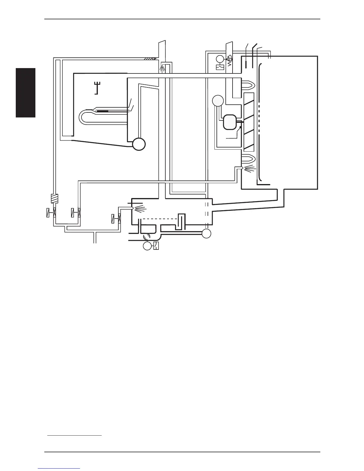
B1 Thermocouple interior cabinet
B2 Thermocouple quenching
B4 Thermocouple humidity
B5 Thermocouple steam generator (preheat, 180°C (356°F) max)
B6-B11 Thermocouples core temperature
F3 Safety thermostat steam generator 160°C (320°F)
F4 Safety thermostat interior cabinet 360°C (680°F)
Y1 Solenoid valve fi lling
Y2 Solenoid valve quenching
Y3 Solenoid valve moistening
M1 Fan motor bottom
M3 Humidity fl ap motor
M4 SC-pump
M6 CleanJet pump
M7 Motor drain valve / ball valve
S2 Level electrode
S4 Micro switch humidity motor
S11 CDS sensor
S12 Micro switch drain valve
P1 Pressure sensor humidity
SCC 201/202 only:
M2 Fan motor top with jumper (fl oor units only)
SCC Electric from 04-2004