42.00.004
42.00.047
1
2
3
4
on
Switch unit ON
On operator PCB set DIP switch 1 to „ON“ position
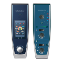
Select service package with timer dial:
Diagnostic Program
Error code history
Running times
Basic settings
Activate with core temperature key the desired service package
Select with timer dial the desired step
Activate selected step by pressing timer key
To de-activate service package set DIP switch 1 to „OFF“ position
.
Switch unit ON
On operator PCB set DIP switch 3 to „ON“ position
First step of function test is displayed
Select desired step of function test with timer dial
Activate selected step by pressing timer key
Activate selected step with core temperature key
To de-activate function test set DIP switch 3 to „OFF“ position.
A)
B)
C)
D)
E)
F)
G)
A)
B)
C)
D)
E)
F)
G)
dP
SE
rt
1
2
3
4
on
Function Test
Service level CM from 04 - 2004
F1
1
2
3
4
on
1
2
3
4
on
Notes:
Er
 Loading...


