-31-
S
C
M
Flue gas analysis: CM gas from 04-2004
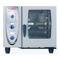
Before you carry out a fl ue gas analysis
check input gas fl ow pressure when burner is running
• Switch on unit. Select any mode and cooking time.
Wait till burner works
• Check input gas fl ow pressure
• See correct values of input fl ow pressure on serial plate
• If necessary adjust gas input pressure
F1
A)
B)
C)
D)
E)
F)
G)
H)
I)
J)
K)
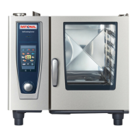
Select any mode and cooking time
Open control panel
Set DIP switch 3 on PCB to „ON“ position
„F1“ is shown on timer display. With timer dial select position F21
Enter position F21 „Steam MAX“ with timer key
Activate position F21 with core temperature key;
NOTE: In this position core temp. key is used as a switch and will
automatically deactivate after 4 minutes.
Gas blower rpm is shown in cabinet temp. display.
Specifi c CO
2
value is shown on timer display, i.e. 9,5
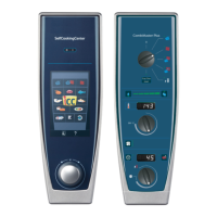
Place fl ue gas testing nozzle in correct fl ue outlet
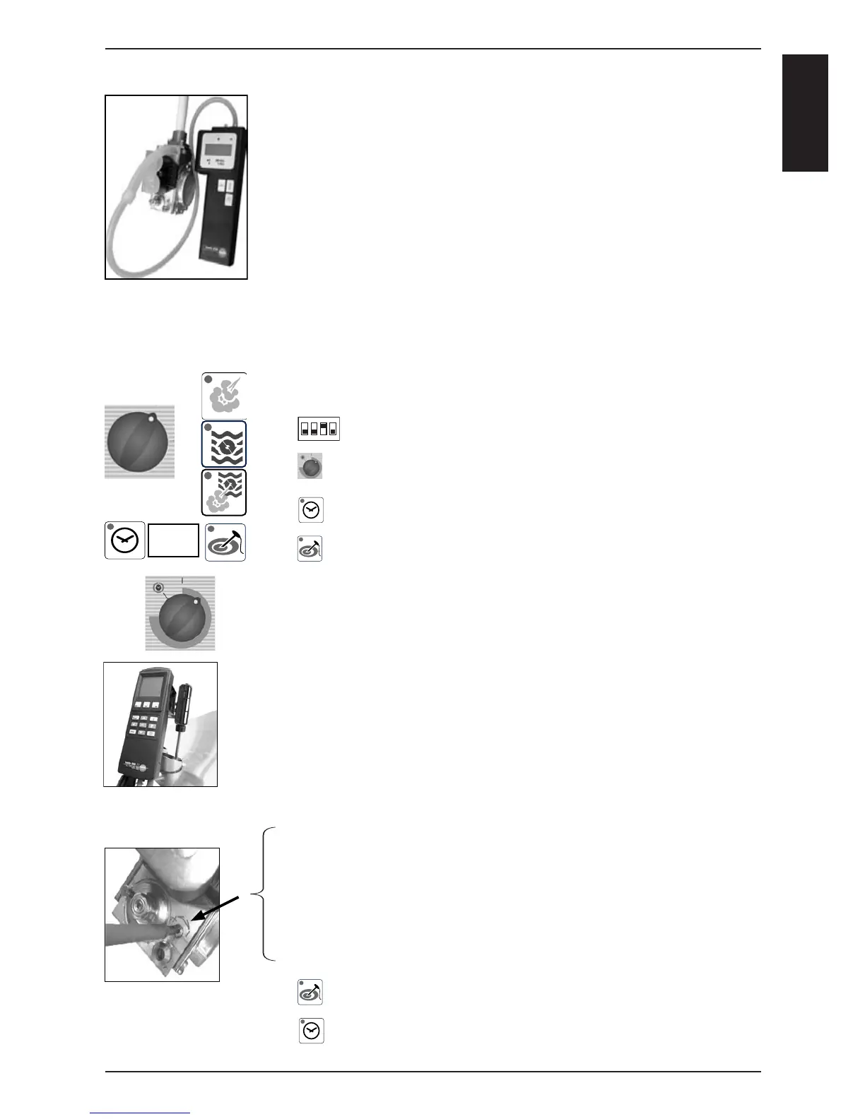
Adjust CO
2
to given value by turning CO
2
screw on gas valve.
You also can fi nd that value on table “Values for burner adjustments“
• If CO
2
value is too low => turn CO
2
screw
anti clockwise (+ direction),
• If CO
2
value is too high => turn CO
2
screw fi rst 2 turns clockwise
(- direction), and than slowly anti clockwise (+ direction) till you get the
indicated CO
2
value. (Screw adjustment tolerance).
• CO value must be below 300ppm
Press core temperature key. Burner will stop.
Leave position F21 „Steam MAX“ with timer key
Flue gas analysis (F21, F24 und F27) at MAX rpm -
Checking CO
2
(F19, F22 and F25) at MIN rpm
NOTE: Components are NOT protected against overload during function test!
1
2
3
4
on