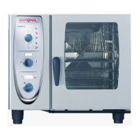
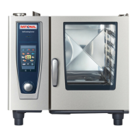
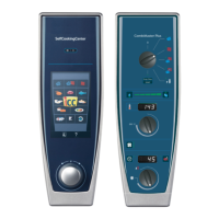
C
M
Mode: Steam 100°C (212°F)
Temp. preset, not adjustable
Function Step
Select Steam mode
Select time or core temperature
Close cabinet door
Check water level inside
steam generator
Preheat steam generator,
if B5 is below 85°C (185°F);
Timer starts after successful preheating
Steam supply up to steam saturation
inside cabinet
Hot Air supply (only 50%) when set
temperature (100°C/212°F) can not be
reached in time by Steam alone
Quenching (set to 70°C/158°F)
Responsible sensor
Reed switch S3
Level electrode S2 in-
side Steam Generator
Thermocouple B5 inside
Steam Generator
Logic on PCB
Quenching sensor B2
(Steam control)
Cabinet sensor B1
Quenching sensor B2
Signal
Door open: 12VDC X27:(1-2)
Door closed: 0VDC X27:(1-2)
X12:(1-4) > 2VAC => no water
X12:(1-4) ~ 0VAC => water
SSR active: 12VDC X24:(1-2)+(5-6)
SSR not act: 0VDC X24:(1-2)+(5-6)
Gas units: Bus signal
SSR active: 12VDC X24:(1-2)+(5-6)
SSR not act.: 0VDC X24:(1-2)+(5-6)
Gas units: Bus signal
SSR active: 12VDC X24:(7-8)
SSR not act.: 0VDC X24:(7-8)
Gas units: Bus signal
B2 above set Temp.: Y2 active
B2 below set Temp.: Y2 not active
Remark
Solenoid Y1 energizes when
no water, 230VAC, X19:(1-3)
Heating off,
if B5 > 180°C (356°F)
Blinking dot in timer
Steam saturation is calculated
by quenching duration and rate
Decision of Hot Air supply by
PCB logic
Y2 active: 230VAC X19:(2-4)
Y2 not act.: 0VAC X19:(2-4)
1
2
3
4
5
6
7
8
9
 Loading...


