Chapter 7
104 Envizio Pro and Envizio Pro II Installation and Operation Manual
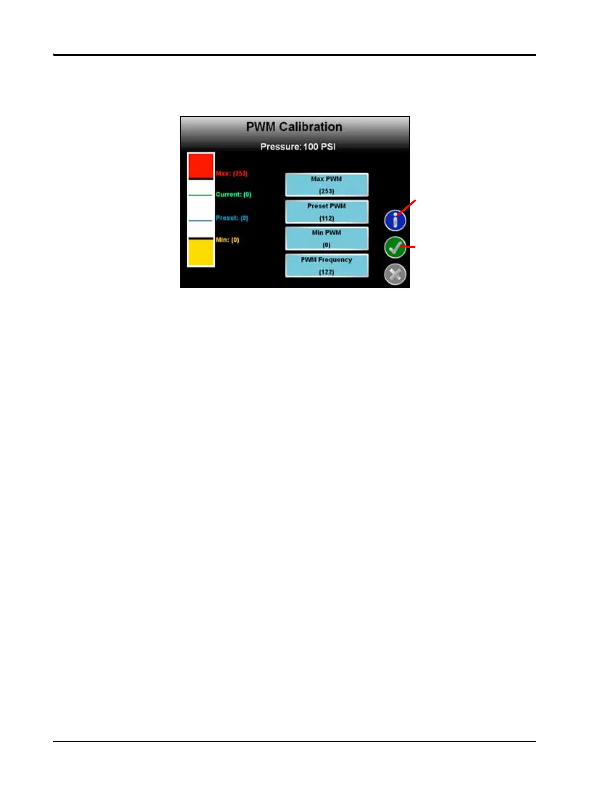
PWM Calibration Screen
In the manual calibration and calibration assistant modes, the PWM Calibration screen will display with the
following options or settings available.
Information. Touch the blue Information icon to display a brief explanation of the settings and options
available on the PWM Calibration screen.
Max PWM. Enter a Max PWM value to set the maximum desired RPM or hydraulic output for a Pulse Width
Modulated (PWM) hydraulic control valve. This setting limits how far the PWM valve will open.
With the machine’s master switch in the on position, increase this value until one of the following conditions is
met:
• The maximum desired pressure is reached in a liquid system
• The maximum desired belt speed is achieved in a granular system
Preset PWM or Standby Pressure. When operating with a PWM valve selected, the preset PWM value sets
how far the valve will stay open to maintain pressure in the system. When the machine’s master switch is off,
the PWM pulse width will remain at the existing value or go to the preset PWM value, whichever is lower.
When operating with a PWM close valve selected, the preset PWM setting is the initial target pulse width when
the master switch is turned on. If this value is set to zero, the pulse width will return to the last value when the
master switch is turned on.
When controlling a liquid product with a PWM valve selected (not PWM close), the standby pressure value sets
the pressure which the system will maintain in the product lines when the master or all boom sections are
toggled off.
Note: The standby pressure setting is only accessible when controlling products in liquid control modes
with a boom pressure transducer detected by the field computer. The node must also be capable
of controlling the ‘PWM Smart Control’ features. Refer to the Feature Settings section on page 110
for details.

 Loading...