9.5 Radar display overview
With your radar scanner connected and the radar in transmit mode,
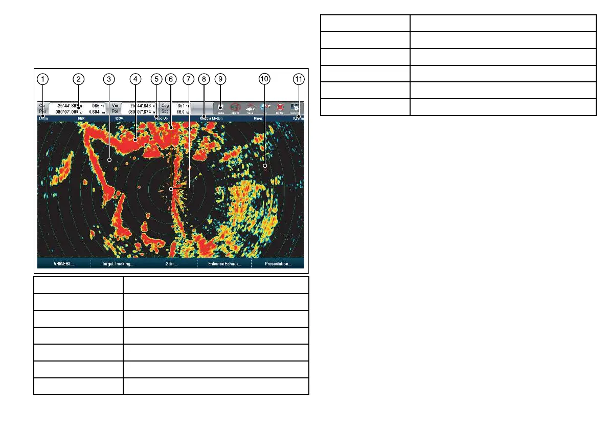
the radar picture provides a map-like representation of the area
in which the radar is operating.
Item Description
1 Range
2 Databar
3 Range ring
4 Land mass
5
Orientation
6
Ship’s Heading Marker (SHM)
Item Description
7
Ship’s position
8 Motion Mode
9 Radar scanner status
10 Waypoint
11 Range ring spacing
Typically, your vessel’s position is at the center of the display, and
its dead ahead bearing is indicated by a vertical heading line, known
as the Ship’s Heading Marker (SHM).
On-screen targets may be large, small, bright or faint, depending on
the size of the object, its orientation and surface. If using a non-HD
digital radome scanner, strongest target returns are displayed in
yellow with weaker returns in 2 shades of blue. If using an HD or
SuperHD digital radar scanner, stronger target returns show as
different colors from a range of 256 colors, providing better clarity.
Be aware that the size of a target on screen is dependent on many
factors and may not necessarily be proportional to its physical size.
Nearby objects may appear to be the same size as distant larger
objects.
With experience, the approximate size of different objects can be
determined by the relative size and brightness of the echoes.
You should bear in mind that the size of each on-screen target is
affected by:
• The physical size of the reecting object.
• The material from which the object is made. Metallic surfaces
reect signals better than non-metallic surfaces.
• Vertical objects such as cliffs reect signals better than sloping
objects such as sandbanks.
• High coastlines and mountainous coastal regions can be observed
at longer radar ranges. Therefore, the rst sight of land may be a
Using radar
123
 Loading...