MODULAR SAFETY INTEGRATED CONTROLLER MOSAIC
8540780 • 30/03/2016 • Rev.26 103
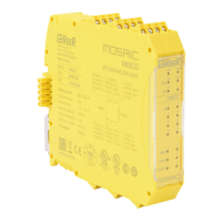
The function block monitors the speed of a device,
generating the Zero to 1 (TRUE) output when the speed is
lower than a selected value.
Parameters
It defines the type of axis controlled by the device.
It will be Linear in the case of a translation and will be Rotary
in the case of motion around an axis.
In the event that the previous parameter is
Linear, the Sensor Type defines the type of sensor connected
to the module inputs. It can be Rotary (e.g. shaft encoder) or
Linear (e.g. optical array). This choice allows to define the
following parameters.
It defines the type of sensor(s) used. The
possible choices are:
- Encoder
- Proximity
- Encoder+Proximity
- Proximity1+ Proximity2
- Encoder1+ Encoder2
If the Axis Type chosen was linear, this field allows you
to enter the sensor pitch to obtain a conversion between
sensor revolutions and distance travelled.
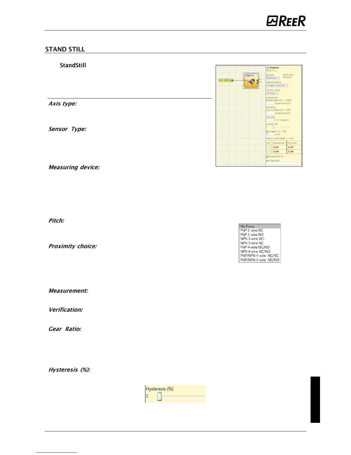
It allows you to choose the type of proximity
sensor from PNP, NPN, Normally Open (NA) and Normally Closed
(NC), with 3 or 4 wires.
(In order to ensure a Performance Level = PLe use a proximity
switch type PNP NO: ref. “Interleaved proximity -> page 25).
Enter in this field the number of pulses/revolution (in the case of rotary sensor)
or µm/pulse (linear sensor) relating to the sensor used
Enter in this field the number of pulses/revolution (in the case of rotary sensor) or
µm/pulse (linear sensor) relating to the second sensor used.
This parameter is active if there are two sensors on the selected axis. This
parameter allows you to enter the ratio between the two sensors. If both sensors are on the
same moving parts, the ratio will be 1 otherwise the number corresponding to the report must
be entered. E.g. there are an encoder and a proximity switch, and the latter is on a moving part
that (due to a gear reduction ratio) rotates at twice the speed of the encoder. Therefore, this
value must be set at 2.
It represents the percentage hysteresis value below which the speed change is
filtered. Enter a value other than 1 to avoid continuous switching as the input changes.
 Loading...


