Output test: This is used to select which test output signals are to be sent to the switch.
This additional control permits detection and management of any short-circuits between
the lines. To enable this control, the test output signals must be configured (amongst
those available).
Test at start-up: If selected this enables the test at start-up of the switch. This test is
performed by opening and closing the switch contact to run a complete function test and
enable the output. This test is only requested at machine start-up (when the unit is
switched on).
Filter (ms): This is used to filter the signals coming from the switch. The filter can be
configured to between 3 and 250ms and eliminates any bouncing on the contacts. The
length of the filter affects the calculation of the unit's total response time.
Enable Error Out: If selected reports a fault detected by the function block.
Item description: This allows a description of the component's function to be entered. The
text is displayed in the top part of the symbol.
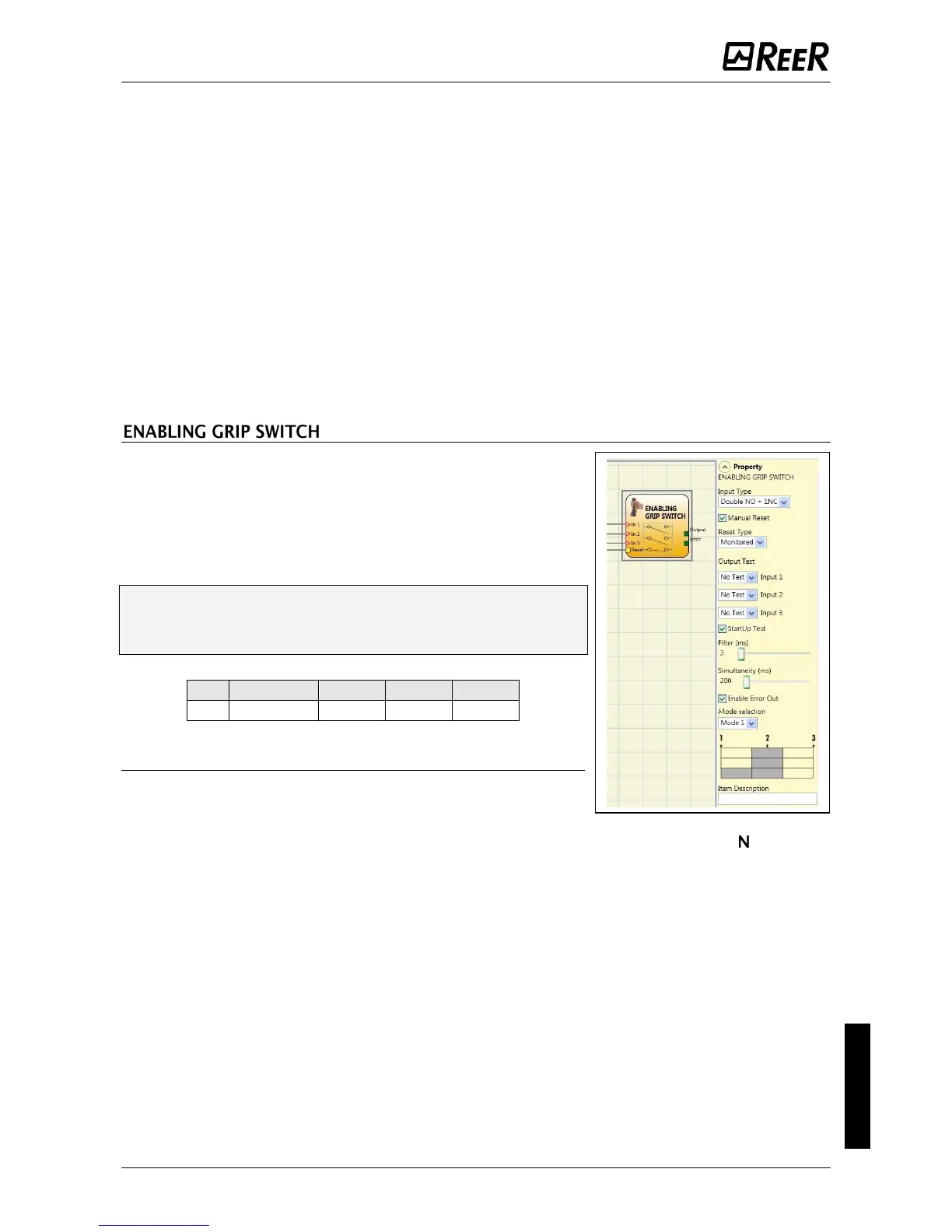
The ENABLING GRIP functional block checks the status of
the In
x
inputs of an enabling grip. If this is not gripped
(position 1) or is gripped completely (position 3), the
OUTPUT will be 0 (FALSE). If it is gripped to middle
position (position 2), the OUTPUT will be 1 (TRUE).
Refer to truth tables at the bottom of the page.
The ENABLING GRIP functional block requires
that the assigned module has a minimum Firmware
version as Table below:
Parameters
Type of inputs:
- Double NO – Permits connection of an enabling grip
with 2 NO contacts.
- Double NO+1NC – Permits connection of an enabling grip switch with 2 O
contacts + 1 NC contact.
Test outputs: Permits selection of the test output signals to be sent to the enabling grip.
This additional control permits detection and management of any short-circuits between
the lines. To enable this control, the test output signals must be configured (amongst
those available).
Power-on test: If selected, enables the power-on test of the external component
(Enabling Grip). To run the test, the device must be gripped and released to carry out a
complete functional check and enable the Output terminal. This control is required only
at machine start-up (power-on of the module).
Simultaneity (ms): always active. Determines that maximum permissible time (msec)
between switching of the various signals from the external contacts of the device.
Filter (ms): Permits filtering of signals from the device control. This filter can be set to
between 3 and 250 ms and eliminates any rebounds on the contacts. The duration of the
filter affects calculation of module total response time.
 Loading...


