MODULAR SAFETY INTEGRATED CONTROLLER MOSAIC
8540780 • 30/03/2016 • Rev.26 139
MOSAIC FAIL CODES
In case of malfunction the Mosaic system transmits to the MSD software a code
corresponding to the error detected by the master M1.
To read the code, proceed as follows:
- connect the Master M1 (indicating FAIL by led) to the PC using the USB cable;
- launch the software MSD;
- use the icon for the connection; a window appears to request the password; enter
the password; a window appears with the error code occurred.
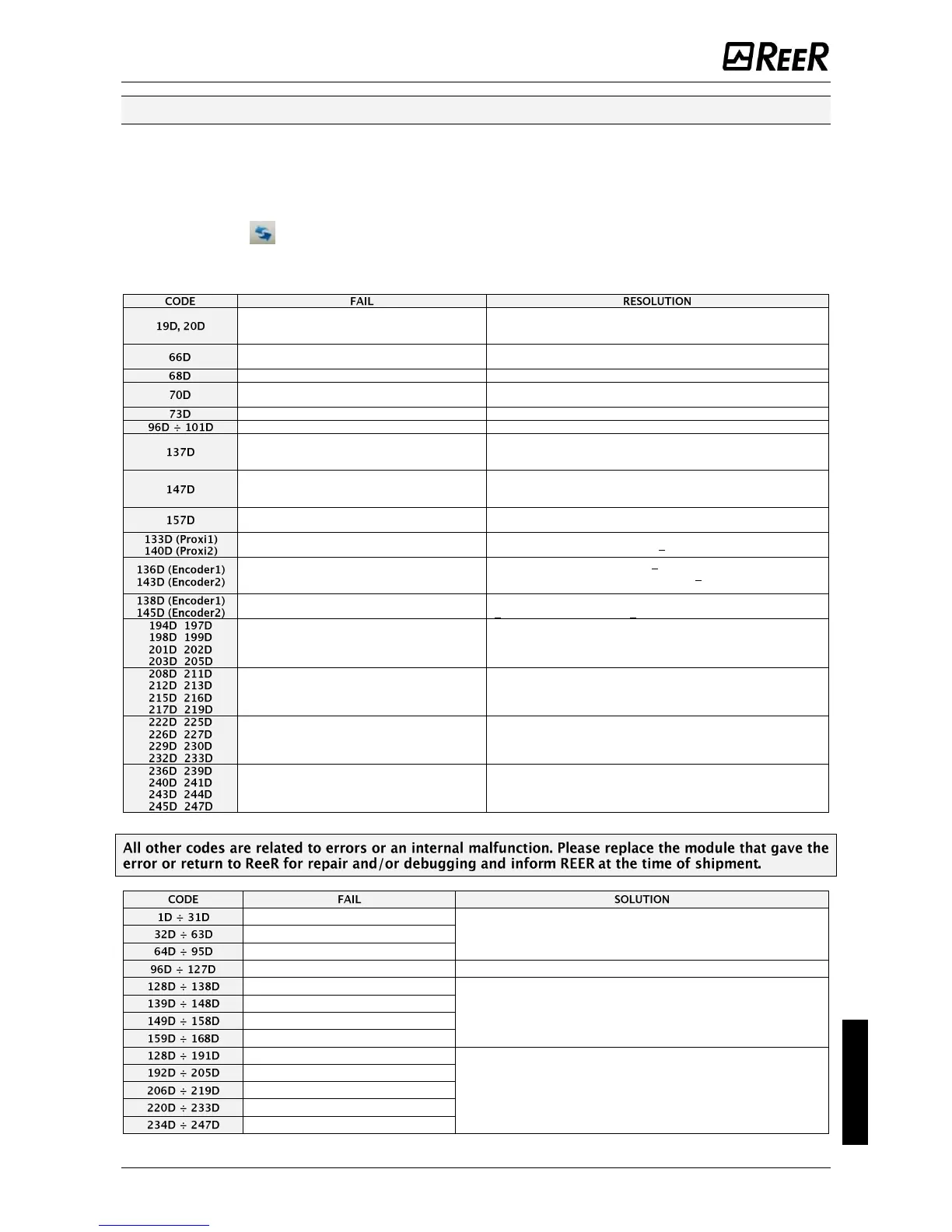
The following table lists all possible errors detected and their solution.
The two M1microcontrollers do not see the
same hw/sw configuration
CHECK CORRECT INSERTION OF M1 AND EXPANSION MODULES
CONNECTORS MSC. POSSIBLY REPLACE THE CONNECTORS.
IF MCT IS PRESENT, CHECK CONNECTION
2 or more same expansion modules with the
same node number
CHECK THE CONNECTIONS PIN 2, 3 EXPANSION MODULES
Exceeded max expansion modules number
DISCONNECT THE MODULES IN EXCESS (MAX14)
One or more modules have detected a change
in the node number
CHECK THE CONNECTIONS OF PIN 2, 3 EXPANSION MODULES
A slave module has detected an external error
CHECK THE ERROR CODE ON MODULE FOR MORE INFORMATION
Errors related to memory MCM
from a MOR4 MOR4S8 -
EDM error on the couple RELAY1 and 2 used in
Category 4
CHECK THE CONNECTION OF THE EXTERNAL FEEDBACK
CONTACTORS
from MOR4 MOR4S8 -
EDM error on the Relay 2 and 3 used in
Category 4
CHECK THE CONNECTION OF THE EXTERNAL FEEDBACK
CONTACTORS
from a form or MOR4 MOR4S8 - EDM error on
the Relay 3 and 4 used in Category 4
CHECK THE CONNECTION OF THE EXTERNAL FEEDBACK
CONTACTORS
From a module MV2, MV1 or MV0:
over-frequency detected on Proximity input
THE INPUT FREQUENCY MUST BE < 5KHz
From a module MV2, MV1 or MV0: encoder
input signals not Standard (duty cycle, phase
displacement)
THE DUTY CYCLE MUST BE: 50%+33% OF THE PERIOD (HTL, TTL).
THE PHASE DISPLACEMENT MUST BE: 90°+33% (HTL, TTL)
(not applicable to SIN / COS)
From a module MV2, MV1 or MV0:
over-frequency detected on Encoder input
THE INPUT FREQUENCY MUST BE:
< 500KHz (TTL, SIN/COS); < 300KHz (HTL).
Errors solid state output OSSD1
CHECK THE OSSD1 CONNECTIONS RELATIVE TO THE MODULE IN
ERROR
Errors solid state output OSSD2
CHECK THE OSSD2 CONNECTIONS RELATIVE TO THE MODULE IN
ERROR
Errors solid state output OSSD3
CHECK THE OSSD3 CONNECTIONS RELATIVE TO THE MODULE IN
ERROR
Errors solid state output OSSD3
CHECK THE OSSD3 CONNECTIONS RELATIVE TO THE MODULE IN
ERROR
TRY TO RESTART SYSTEM. IF ERROR PERSISTS, SEND UNIT TO REER
LABORATORY FOR REPAIR.
Communication error between units
Error module MOR4 relay 1
TRY TO RESTART SYSTEM. IF ERROR PERSISTS, SEND UNIT TO REER
LABORATORY FOR REPAIR.
Error module MOR4 relay 2
Error module MOR4 relay 3
Error module MOR4 relay 4
Error units MV encoder interface
TRY TO RESTART SYSTEM. IF ERROR PERSISTS, SEND UNIT TO REER
LABORATORY FOR REPAIR.
 Loading...


