MODULAR SAFETY INTEGRATED CONTROLLER MOSAIC
8540780 • 30/03/2016 • Rev.26 29
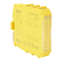
250ms < t1< 5s
t2 = 250ms
SAFETY RELAYS (MR2, MR4, MOR4, MOR4S8)
Characteristics of the output circuit.
The MR2/MR4 units use guided contact safety relays, each of which provides
.
The MR2 unit uses two safety relays and the MR4 uses four.
The MOR4/MOR4S8 units use four guided-contact safety relays. Each relay provides one
NO contact monitored by the module logic through internal FBK contact.
Refer to the "RELAY" section to check the possible MOR4/MOR4S8 operation modes
configurable with MSD software.
Minimum switchable voltage
Minimum switchable current
Maximum switchable voltage (DC)
Maximum switchable voltage (AC)
Maximum switchable current
Mechanical life of contacts
Table 18
To guarantee correct isolation and avoid the risk of premature ageing of or damage
to the relays, each output line must be protected using a fast acting 4A fuse and the
load characteristics must be consistent with those specified in Table 12.
See the "MR2/MR4" section (for further details on these relays).
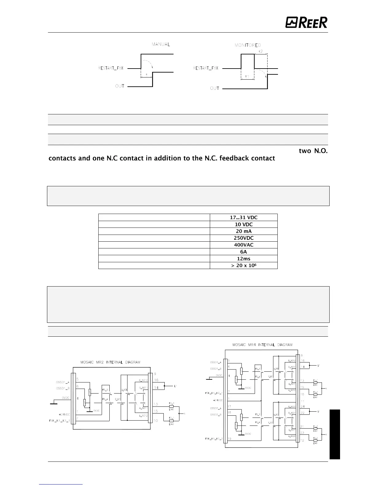
MR2/MR4 internal contacts diagram
Figure 7
 Loading...


