WARNING: If the Manual Reset is active, a consecutive Input have to be used.
Example : Input 1 and Input 2 are used for the fuctional block, then Input 3 have to
be used for the Reset Input.
Output test: This is used to select which test output signals are to be sent to the
component contacts. This additional control permits detection and management of any
short-circuits between the lines. To enable this control, the test output signals must be
configured (amongst those available).
Test at start-up: If selected this enables the test at start-up of the external component.
This test is performed by opening the mobile guard or safety gate to run a complete
function test and enable the output. This test is only requested at machine start-up (when
the unit is switched on).
Filter (ms): This is used to filter the signals coming from the external contacts. The filter
can be configured to between 3 and 250 ms and eliminates any bouncing on the
contacts. The length of the filter affects the calculation of the unit's total response time.
Enable Error Out: If selected reports a fault detected by the function block.
Item description: This allows a description of the component's function to be entered. The
text is displayed in the top part of the symbol.
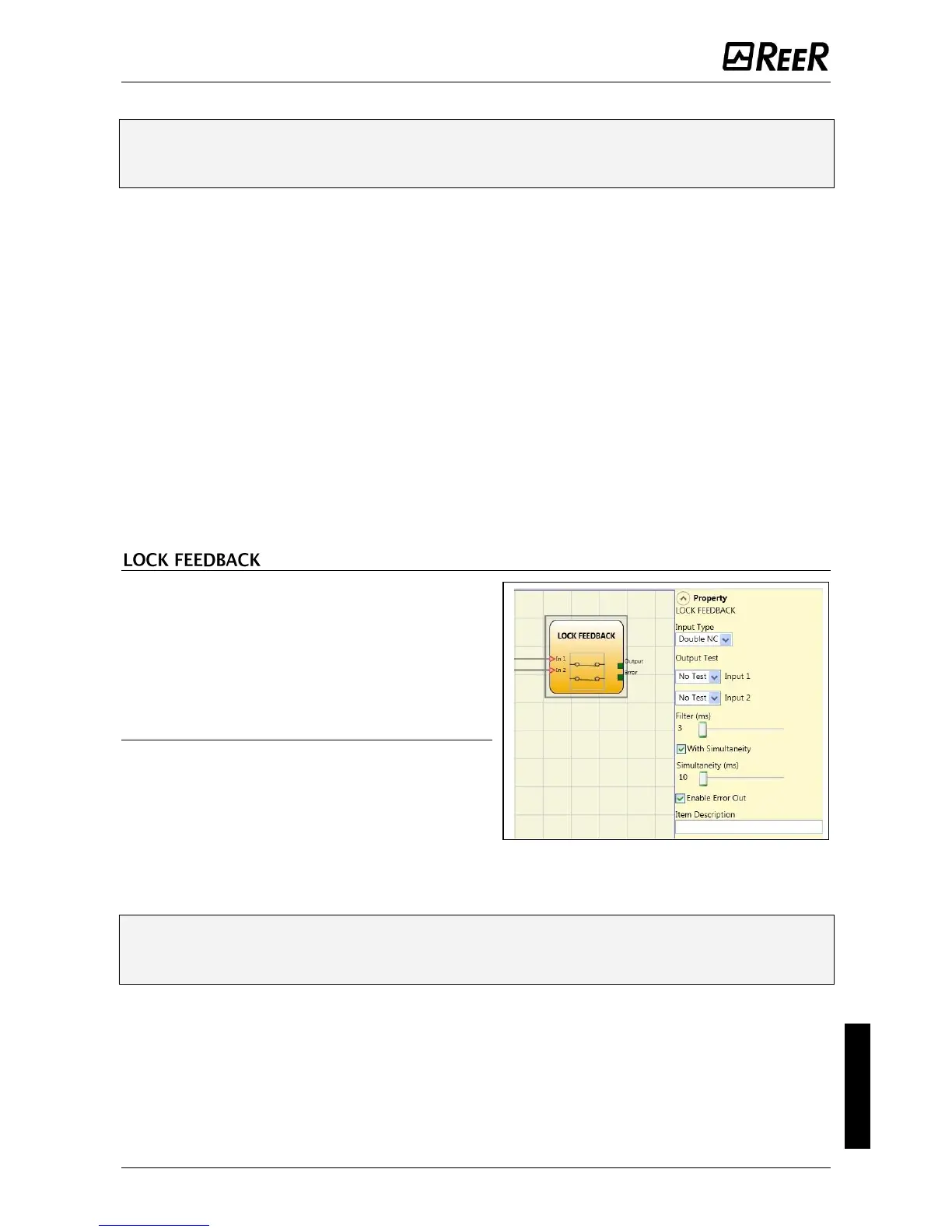
The function block LOCK FEEDBACK verifies
the lock status of the guard lock device for
mobile guard or safety gate. In the case where
the inputs indicate that the guard is locked
the Output will be 1 (TRUE). Otherwise the
output is 0 (FALSE).
Parameters
Input type
- Single NC – Allows connection of
components with one NC contact;
- Double NC – Allows connection of
components with two NC contacts.
- Double NC/NO – Allows connection of
components with one NO contact and one NC.
With inactive input (guard unlocked), connect:
- Contact NO to terminal corresponding to IN1
- Contact NC to terminal corresponding to IN2.
Output test: This is used to select which test output signals are to be sent to the
component contacts. This additional control permits detection and management of any
short-circuits between the lines. To enable this control, the test output signals must be
configured (amongst those available).
Filter (ms): This is used to filter the signals coming from the external contacts. The filter
can be configured to between 3 and 250 ms and eliminates any bouncing on the
contacts. The length of the filter affects the calculation of the unit's total response time.
 Loading...


