EasyManuals Logo

Reer MOSAIC Master M1 User Manual

Reer MOSAIC Master M1
143 pages
To Next Page IconTo Next Page
To Previous Page IconTo Previous Page
Page #25 background imageLoading...
Page #25 background image
MODULAR SAFETY INTEGRATED CONTROLLER MOSAIC
8540780 • 30/03/2016 • Rev.26 25
English
MASTER ENABLE
The MOSAIC M1 master has two inputs: MASTER_ENABLE1 and MASTER_ENABLE2.
These signals must both be permanently set to logic level 1 (24VDC) for the MOSAIC
to operate. If the user needs to disable the MOSAIC simply lower these inputs to
logic level 0 (0VDC).
NODE SEL
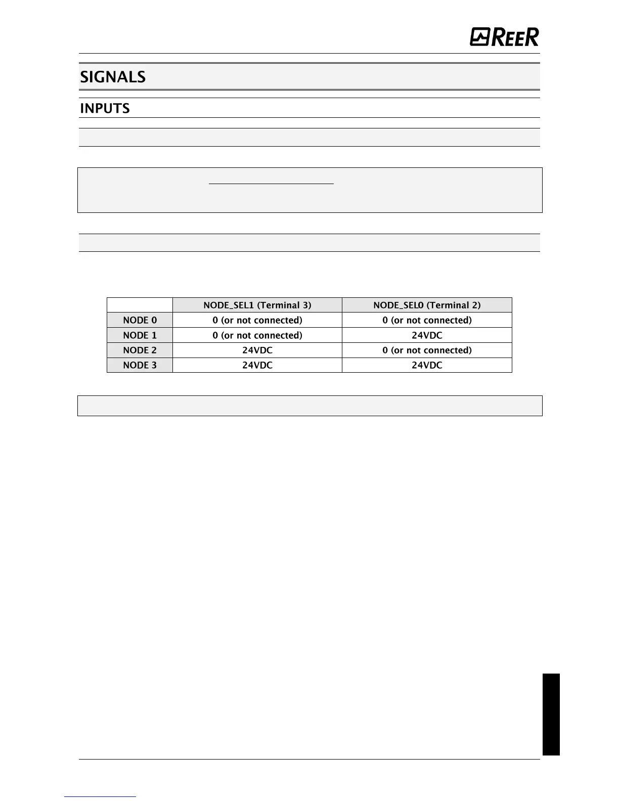
The NODE_SEL0 and NODE_SEL1 inputs (on the SLAVE units) are used to attribute a
physical address to the slave units with the connections shown in Table 15:
Table 15
It is not allowed to use the same physical address on two units of the same type.

Table of Contents

Questions and Answers:

Question and Answer IconNeed help?

Do you have a question about the Reer MOSAIC Master M1 and is the answer not in the manual?

Reer MOSAIC Master M1 Specifications

General IconGeneral
BrandReer
ModelMOSAIC Master M1
CategoryController
LanguageEnglish

Related product manuals