OUTPUT OBJECTS
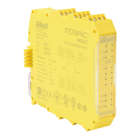
OSSD safety outputs which use semiconductor
technology do not require maintenance, Output1
and Output2 supply 24Vdc if the In is 1 (TRUE) and
vice versa 0Vdc if the In is 0 (FALSE).
Each pair of OSSD outputs has a relative
RESTART_FBK input. This input must always
be connected as indicated in the
RESTART_FBK paragraph.
Parameters
Manual Reset: If selected this enables the request to reset each time the input signal falls.
Otherwise, output enabling directly follows In input conditions.
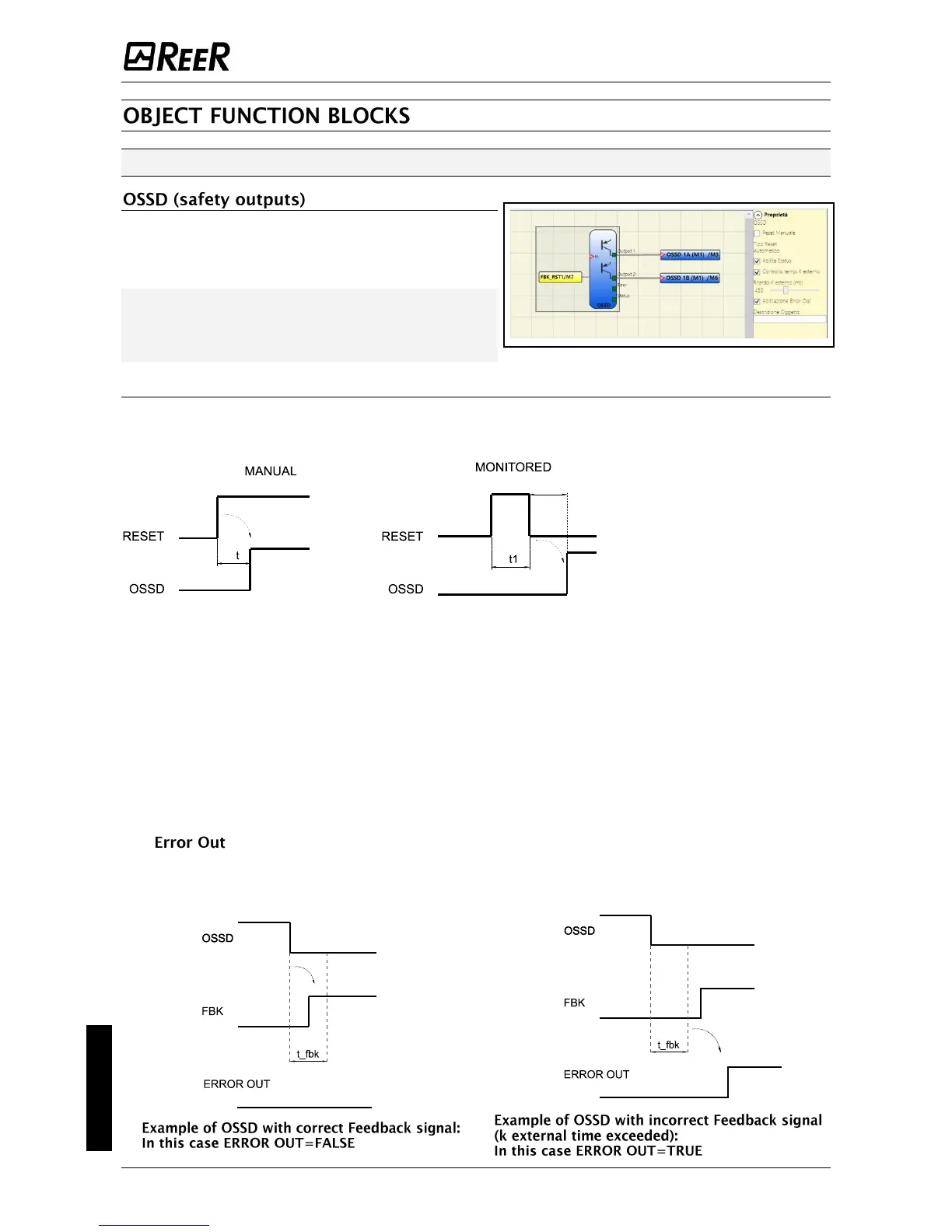
There are two types of reset:
Manual and Monitored. In
selecting the Manual option
only signal transition from 0
to 1 is verified. If the
Monitored option is selected,
the double transition from 0
to 1 and back to 0 is verified.
Enable Status: If selected,
enables the connection of the
current OSSD state to any
point on the screen.
K external time check: If selected, enables the setting of the time window within which the external
feedback signal is to be monitored (according to output conditions).
With high level (TRUE) OUTPUT, the FBK signal must be at low level (FALSE) and vice versa, within
the set time.
Otherwise, OUTPUT is set to low level (FALSE) and the error is indicated on the master M1 by the
flashing CLEAR LED corresponding to the OSSD in error.
Enable Error Out If selected, enables the ERROR OUT output. This output is set to high level (TRUE)
when an external FBK error is detected.
The signal is reset in case of one of the following events:
1. Switching on and switching off of system.
2. Activation of the RESET M1 operator.
 Loading...


