1) The input must always be connected to a (feedback coil lock) input
element.
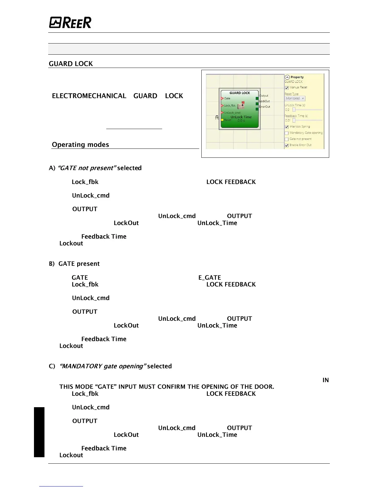
2) The input can be connected freely in the diagram and determines the request to
unlock (when in LL1 state).
3) The signal of this element is 1 (TRUE) if the guard is closed and locked. When an
unlock command is applied to the input, the signal is set to "0" and the
guard is unlocked ( output) after a time configurable as parameter. This
output goes to 0 (FALSE) even when error conditions are present (eg. open door with lock
locked, that exceeds the maximum allowed, ...).
4) signal controls the locking/unlocking of the guard.
1) The input must always be connected to an lock input (guard feedback).
2) The input must always be connected to a (feedback coil lock) input
element.
3) The input can be connected freely in the diagram and determines the request to
unlock (when in LL1 state).
4) The signal of this element is 1 (TRUE) if the guard is closed and locked. When an
unlock command is applied to the input, the signal is set to "0" and the
guard is unlocked ( output) after a time configurable as parameter. This
output goes to 0 (FALSE) even when error conditions are present (eg. open door with lock
locked, that exceeds the maximum allowed, ...).
5) signal controls the locking/unlocking of the guard.
1) The GATE Input must always be connected to a E_GATE block input (feedback of the door).
2) The input must always be connected to a (feedback coil lock) input
element.
3) The input can be connected freely in the diagram and determines the request to
unlock (when in LL1 state).
4) The signal of this element is 1 (TRUE) if the guard is closed and locked. When an
unlock command is applied to the input, the signal is set to "0" and the
guard is unlocked ( output) after a time configurable as parameter. This
output goes to 0 (FALSE) even when error conditions are present (eg. open door with lock
locked, that exceeds the maximum allowed, ...).
5) signal controls the locking/unlocking of the guard.
 Loading...


