The function block monitors the speed of a
device generating an output 0 (FALSE) when the measured
speed exceeds a predetermined threshold. In the case in which
the speed is below the predetermined threshold the output will
be 1 (TRUE).
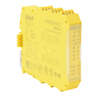
Parameters
It defines the type of axis controlled by the device. It
will be Linear in the case of a translation and will be Rotary in
the case of motion around an axis.
In the event that the previous parameter is
Linear, the Sensor Type defines the type of sensor connected to
the module inputs. It can be Rotary (e.g. shaft encoder) or
Linear (e.g. optical array). This choice allows to define the
following parameters.
It defines the type of sensor(s) used. The
possible choices are:
- Encoder
- Proximity
- Encoder+Proximity
- Proximity1+ Proximity2
- Encoder1+ Encoder2
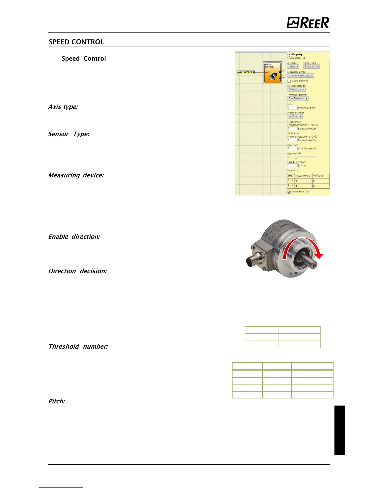
Enabling this parameter, the DIR output is
enabled on the function block. This output will be 1 (TRUE)
when the axis rotates Counterclockwise and will be 0 (FALSE)
when the axis rotates Clockwise
It defines the direction of rotation for
which the set thresholds are made active. The possible choices
are:
- Bidirectional
- Clockwise
- Counterclockwise
If Bidirectional is selected, the excess of the set threshold is
detected whether the axis rotates clockwise or
counterclockwise. Selecting Clockwise or Counterclockwise, this
is detected only when the axis rotates in the selected direction.
It allows you to enter the number of
thresholds for the maximum value of speed. Changing this
value will increase/decrease the number of thresholds that can
be entered from a minimum of 1 to a maximum of 4. In the
case of thresholds greater than 1, the input pins for the
selection of the specific threshold will appear in the lower part
of the function block.
If the Axis Type chosen was linear, this field allows you
to enter the sensor pitch to obtain a conversion between sensor
revolutions and distance travelled.
 Loading...


