MODULAR SAFETY INTEGRATED CONTROLLER MOSAIC
106 8540780 • 30/03/2016 • Rev.26
It allows you to choose the type of proximity
sensor from PNP, NPN, Normally Open (NA) and Normally Closed
(NC), with 3 or 4 wires.
(In order to ensure a Performance Level = PLe use a proximity
switch type PNP NO: ref. “Interleaved proximity -> page 26).
Enter in this field the number of pulses/revolution (in the case of rotary sensor)
or µm/pulse (linear sensor) relating to the sensor used
Enter in this field the number of pulses/revolution (in the case of rotary sensor) or
µm/pulse (linear sensor) relating to the second sensor used.
This parameter is active if there are two sensors on the selected axis. This
parameter allows you to enter the ratio between the two sensors. If both sensors are on the
same moving parts, the ratio will be 1 otherwise the number corresponding to the report must
be entered. E.g. there are an encoder and a proximity switch, and the latter is on a moving part
that (due to a gear reduction ratio) rotates at twice the speed of the encoder. Therefore, this
value must be set at 2.
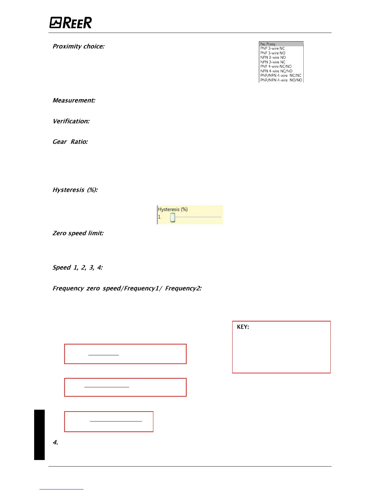
It represents the percentage hysteresis value below which the speed change is
filtered. Enter a value other than 1 to avoid continuous switching as the input changes.
Enter in this field the maximum speed value above which the output of the function block (ZERO)
will be 0 (FALSE). If the measured speed is less than the set value, the output (ZERO) of the
function block will be 1 (TRUE).
Enter in this field the maximum speed value above which the function block
output (OVER) will be 0 (FALSE). If the measured speed is less than the set value, the function
block output (OVER) will be 1 (TRUE).
It shows
the maximum calculated frequency values fM and fm
(decreased by the hysteresis set). If the displayed value is
GREEN, the calculation of frequency gave a positive result.
If the displayed value is RED, it is necessary to change the
parameters given in the following formulas.
1. Rotary axis, rotary sensor. The frequency obtained is:
v][pulses/resolutionRe
60
[rev/min]rpm
[Hz]f
2. Linear axis, rotary sensor. The frequency obtained is:
v][pulses/reRe
[mm/rev]*60
1000*[m/min]
[Hz] solution
pitch
speed
f
3. Linear axis, linear sensor. The frequency obtained is:
[µm/pulse]solutionRe
1000*[mm/s]speed
[Hz]f
Hysteresis. To be changed only if: fM=green; fm=red
f = frequency
Rpm = rotational speed
Resolution = measurement
Speed = linear speed
Pitch = sensor pitch
 Loading...


