PG-FP5 CHAPTER 6 USAGE IN STANDALONE MODE
R20UT0008EJ0400 Rev. 4.00 Page 125 of 240
Jul 15, 2010
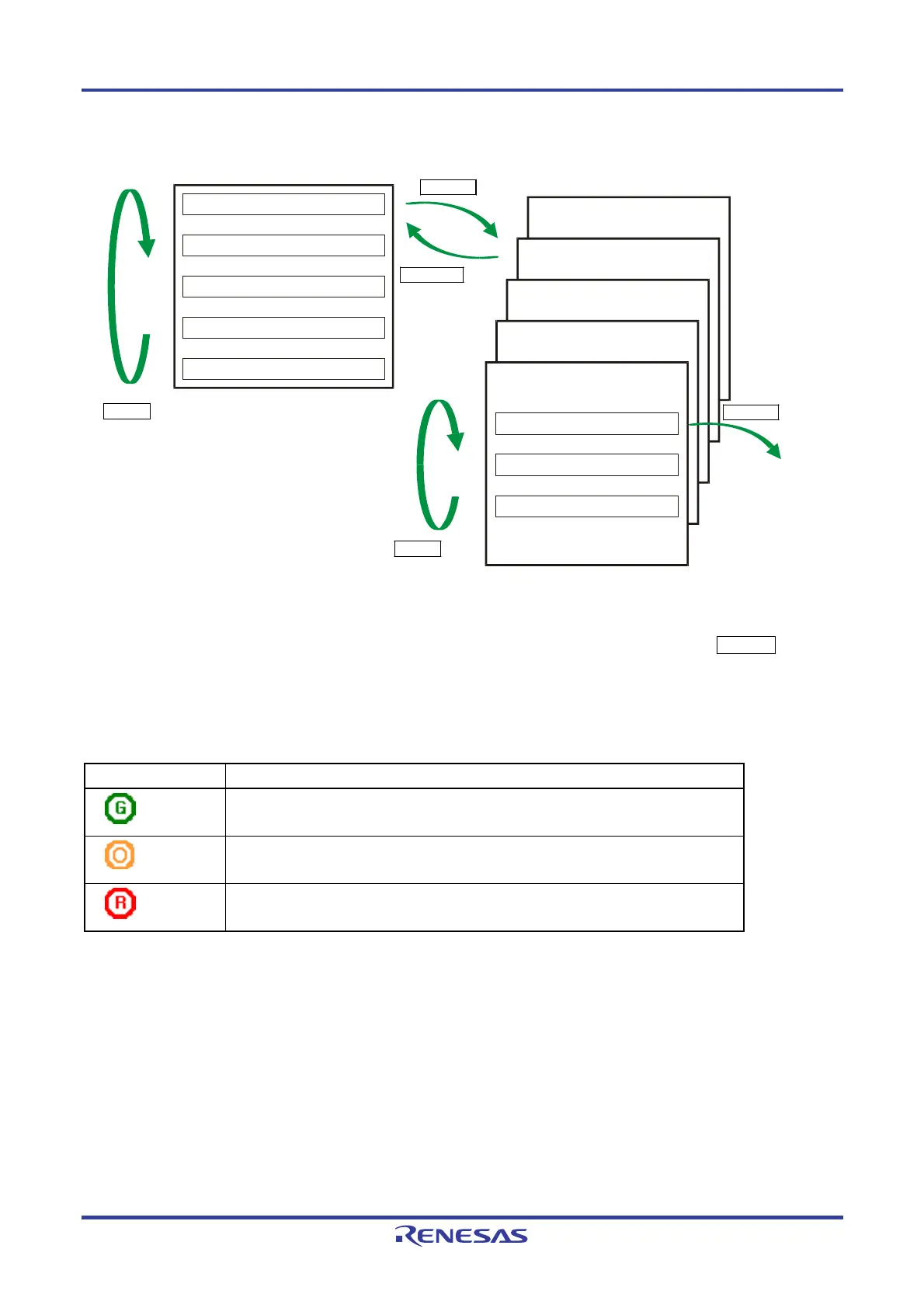
Figure 6-1. Menu Status Transition by Button Input
Commands
Main menu
Submenu
Commands
Voltage Setting
Utility/Misc.
Option Setting
Type Setting
>
>
>
>
>
Reset FP5 >
..
..
Type Setting
Option Setting
Voltage Setting
Utility/Misc.
ENTER button
CANCEL button
NEXT button
NEXT button
ENTER button
Command
execution
On the main menu level, the FP5 shows the menu items that can be selected. On the submenu level, the first line in
the message display shows the menu item and the second line shows the response from the FP5, if any.
A command prompt ‘>’ displayed at the end of a menu line indicates that it is selectable with the ENTER button, or
that the menu (command) can be executed. If the command prompt ‘>’ is not displayed at the end of a menu line, it
means that the function is available only for display.
When power to the FP5 is turned on, the POWER LED turns on and ‘Commands >’ is displayed in the message display.
The status LEDs indicate the status of communication with the device and the result of execution, as follows.
Status LED Status
Green
The selected command has been executed correctly.
The command that has been correctly executed is displayed in the message display.
Orange
The selected command is under execution.
The detailed execution status is displayed in the message display.
Red
The selected command has been terminated by an error.
The error details are displayed in the message display.
Remark For details on the errors displayed in the message display, refer to error message A.4 Error Messages
Displayed in FP5 Message Display.
 Loading...


