PG-FP5 CHAPTER 10 NOTES ON TARGET SYSTEM DESIGN
R20UT0008EJ0400 Rev. 4.00 Page 194 of 240
Jul 15, 2010
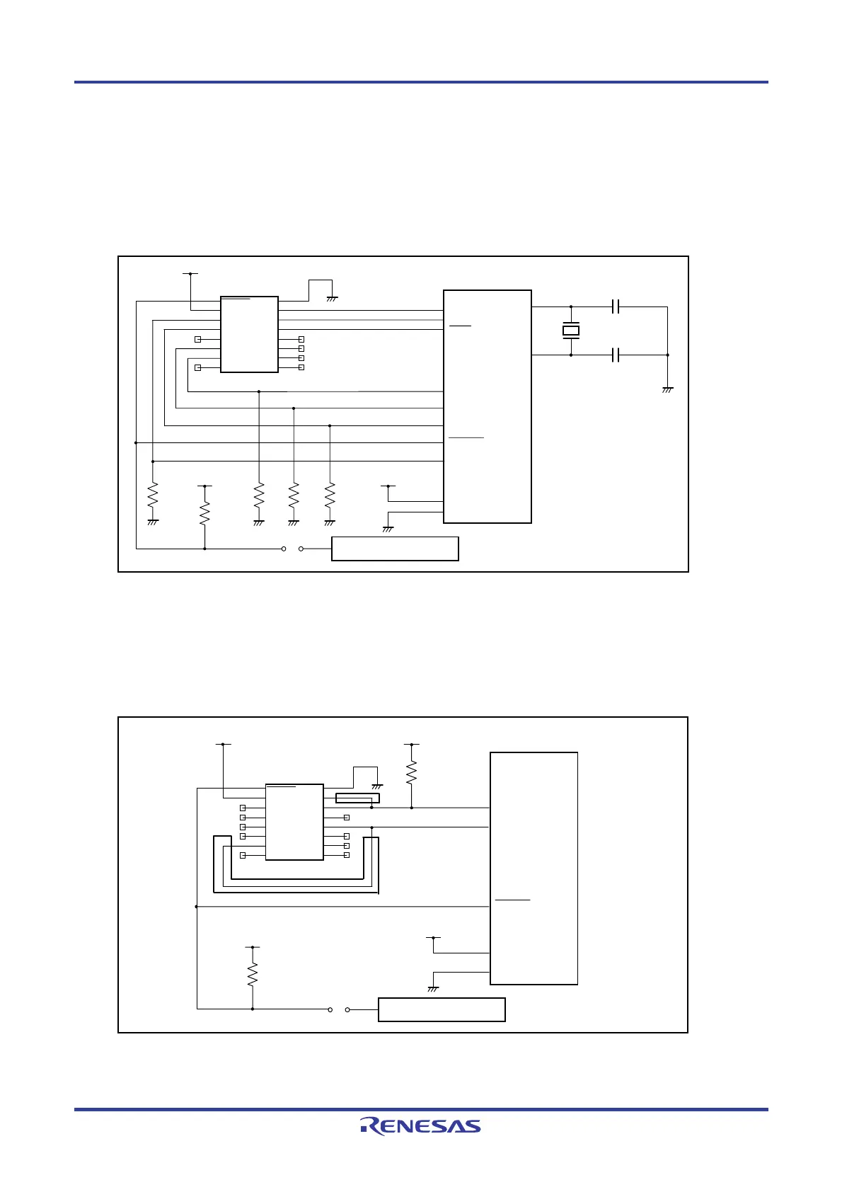
The following are examples of interface circuits. Refer to the recommended design for the connection of pins in the
target device.
<1> SIO-H/S (3-wire clocked communication port, with handshake)
Figure 10-1. SIO-H/S Interface Circuit Example
Notes 1. Pin used in internal single-power-supply flash memory microcontroller
2. Pin used in internal two-power-supply flash memory microcontroller
<2> 78K0S (Single-wire UART)
Figure 10-2. Circuit Example for 78K0S (Single-wire UART)
Note These pins do not need to be shorted when using the FP5. Short them if necessary.
Note 1
Note 1
Note 2
FLMD1
VCC
VCC
JUMPER
User reset circuit
V
CC
R
Connector
7616-5002PL
Target device
Y
C
C
2
4
6
8
10
12
14
16
RESET
V
DD
VPP
H/S
VDE
FLMD1
FLMD0
NC
GND
SI/RxD
SO/TxD
SCK
CLK
VDD2
RFU-1
NC
1
3
5
7
9
11
13
15
X1
X2
FLMD0
V
DD
VSS
RESET
R R
SO
SI
SCK
R
VPP
R
HS
VCC
VCC
VCC
Connecto
7616-5002PL
Tar
et device
2
4
6
8
10
12
14
16
RESET
VDD
VPP
H/S
VDE
FLMD1
FLMD0
NC
GND
SI/RxD
SO/TxD
SC
CL
VDD2
RFU-1
NC
1
3
5
7
9
11
13
15
VDD
VSS
X2
X1
JUMPER
User reset circuit
VCC
R
RESET
R
Note
Note
 Loading...


