PG-FP5 CHAPTER 10 NOTES ON TARGET SYSTEM DESIGN
R20UT0008EJ0400 Rev. 4.00 Page 196 of 240
Jul 15, 2010
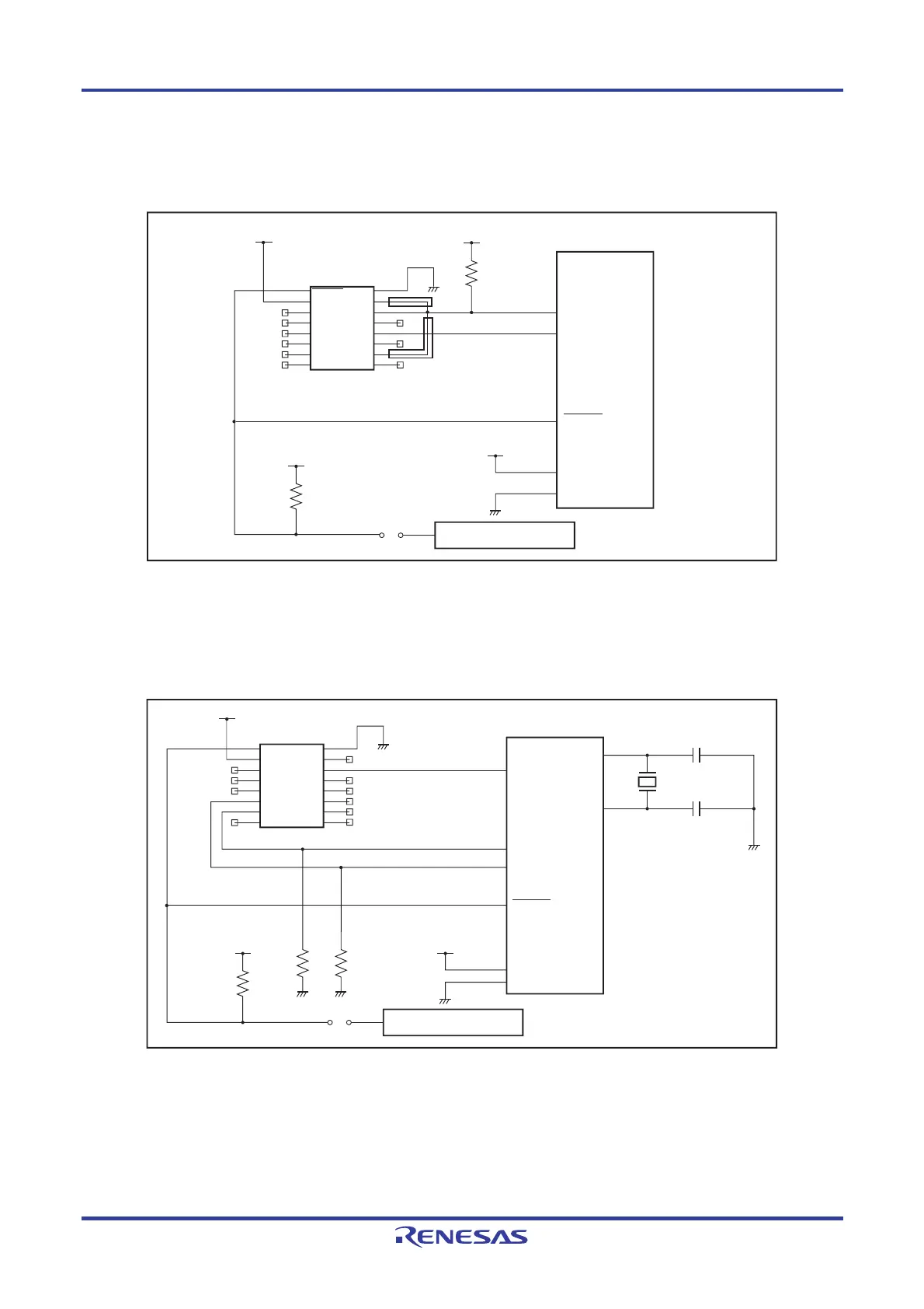
<5> 78K0 (TOOLCx, TOOLDx)
Figure 10-5. Circuit Example for 78K0 (TOOLCx, TOOLDx)
VCC
VCC
VCC
Connector
7616-5002PL
Target device
2
4
6
8
10
12
14
16
RESET
V
DD
V
PP
H/S
VDE
FLMD1
FLMD0
NC
GND
SI/RxD
SO/TxD
SCK
CLK
V
DD2
RFU-1
NC
1
3
5
7
9
11
13
15
VDD
VSS
TOOLDx
TOOLCx
JUMPER
User reset circuit
VCC
R
RESET
R
Note
Note
Note These pins do not need to be shorted when using the FP5. Short them if necessary.
<6> V850 (Single-wire UART)
Figure 10-6. Circuit Example for V850 (Single-wire UART)
FLMD1
V
CC
V
CC
JUMPER
User reset circuit
V
CC
R
Connector
7616-5002PL
Target device
Y
C
C
2
4
6
8
10
12
14
16
RESET
V
DD
V
PP
H/S
VDE
FLMD1
FLMD0
NC
GND
SI/RxD
SO/TxD
SCK
CLK
V
DD2
RFU-1
NC
1
3
5
7
9
11
13
15
X1
X2
FLMD0
V
DD
V
SS
RESET
R R
FLUR0RX/
FLUR0TX
Note
Note The pin names might differ depending on the target device. For details about the actual pin names, see the
user’s manual of each target device.
<R>